Chery Tiggo. Manual - part 342
Operation
The steering column is the mechanical linkage between the steering wheel and the steering gear. The steering col-
umn shaft then connects the steering column to the steering gear. The tilt function of the steering column is con-
trolled by a mechanical lever on the underside of the steering column, which uses a cam to lock and unlock the
steering column.
Specifications
Torque Specifications
DESCRIPTION
TORQUE (N·m)
Steering Wheel Lock Nut
25 - 30
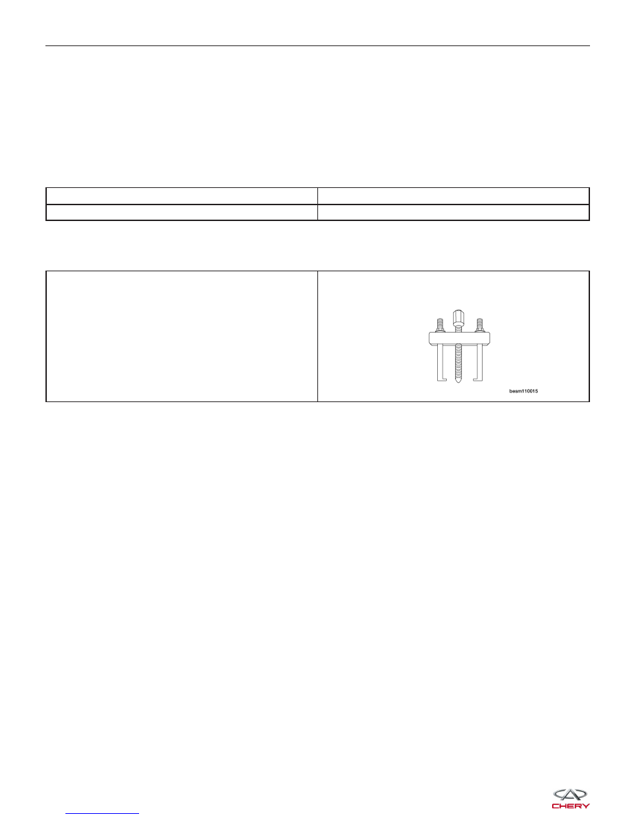
Special Tool
Steering Wheel Puller
GENERAL INFORMATION