Chery Tiggo. Manual - part 333


  Index      Chery     Chery Tiggo - service repair manual 2009 year


Search            


Content   ..  331  332  333  334   ..


Chery Tiggo. Manual - part 333


Specifications

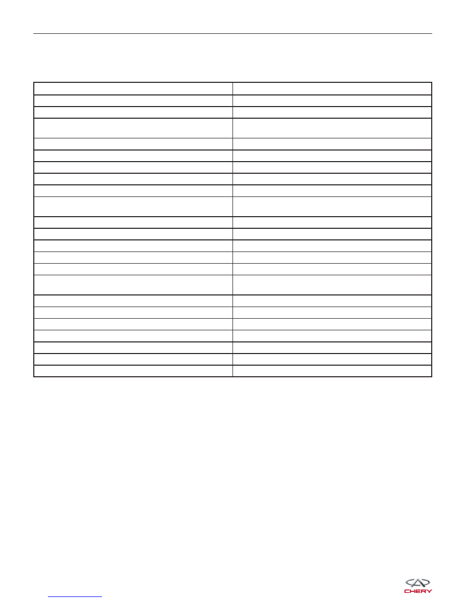
Torque Specifications

DESCRIPTION

TORQUE (N·m)

Rear Stabilizer Bar Link

40 - 50

Lower Suspension Lever

40 - 50

Rear Shock Absorber to Rear Shock Absorber Mounting
Bracket

40 - 50

Control Arm Knuckle Pin to Control Arm

140 - 160

Rear Axle Front Suspension to Rear Sub-Frame

115 - 125

Rear Axle Front Suspension to Rear Driving Axle

75 - 85

Control Arm And Sub-Frame

170 - 190

Rear Rubber Buffer Assembly to Vehicle Body

22 - 28

Rear Axle Rear Suspension Cushion Assembly to Rear
Axle

75 - 85

Upper Link to Rear Sub-Frame

100 - 120

Lower Control Arm to Rear Sub-Frame

100 - 120

Lower Control Arm to Trailing Arm

100 - 120

Upper Link to Trailing Arm

100 - 120

Rear Suspension to Bracket

115 - 125

Rear Suspension, Longitudinal Beam Of Engine And
Sub-Frame

75 - 85

Rear Stabilizer Bar Clamp to Vehicle Body

22 - 28

Rear Trailing Arm to Vehicle Body

140 - 160

Soft Gasket And Bracket Of Rear Suspension

110 - 130

Sub-Frame And Gasket Of Vehicle (Rear) Body

170 - 190

Sub-Frame And Longitudinal Beam Assembly

75 - 85

Upper End Of Rear Shock Absorber to Vehicle Body

22 - 28

Wheel Mounting Nut                                                                                                          110

GENERAL INFORMATION


DIAGNOSIS & TESTING

Vehicle Inspection

Inspect the rear axle for the following:

• Check the rear axle for loose bearings.

• Check the rear axle hub for any damage or excessive runout.

Vibration At High Speed

This problem could be a result of the following:

• Foreign material (mud, etc.) packed on the backside of the wheel(s).

• Out of balance tires or wheels.

• Improper tire or wheel runout.

10


ON-VEHICLE SERVICE

Rear Lower Control Arm

Removal & Installation

1. Raise and support the vehicle.

2. Remove the bolt that joins rear stabilizer bar and rear suspension lower control arm (See Rear Stabilizer Bar

Link Removal & Installation in Section 10 Suspension).

3. Remove the retaining bolt (1) connecting the lower

control arm and rear trailing arm.
(Tighten: Lower control arm to rear trailing arm bolt
to 80 - 100 N·m)

4. Remove the retaining bolt (1) connecting the upper

control arm and rear sub-frame assembly.
(Tighten: Upper control arm and rear sub-frame
assembly bolt to 80 - 100 N·m)

5. Installation is in the reverse order of removal.

Installation Notes:
• After installation, each bolt must be tightened to the

required tightening torque.

LTSM100061

LTSM100066


Rear Upper Control Arm

Removal & Installation

1. Raise and support the vehicle.

2. Remove the retaining bolt (1) connecting the upper

control arm and rear trailing arm.
(Tighten: Upper control arm to rear trailing arm bolt
to 80 - 100 N·m)

3. Remove the retaining bolt (1) connecting the upper

control arm and rear sub-frame assembly.
(Tighten: Upper control arm to rear sub-frame
assembly bolt to 80 - 100 N·m)

4. Installation is in the reverse order of removal.

Installation Notes:
• After installation, each bolt must be tightened to the

required tightening torque.

ON-VEHICLE SERVICE

LTSM100068

LTSM100065

10


Content   ..  331  332  333  334   ..