Chery Tiggo. Manual - part 316
Special Tools
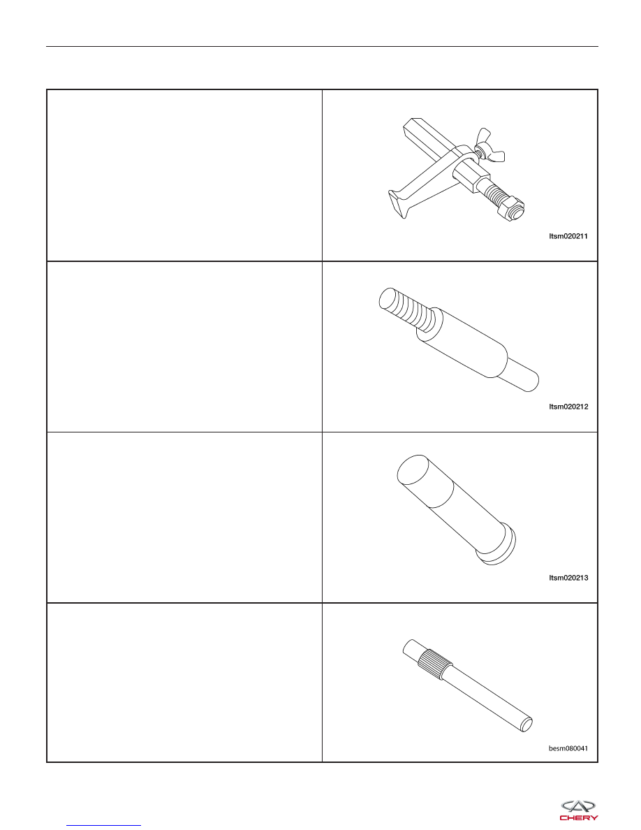
Flywheel Fixture
09924 - 17810
Bearing Extractor
09917 - 58010
Input Shaft Bearing Mounting Device
09925 -98210
Clutch Pressure Plate Installer
CH-20014
GENERAL INFORMATION
|
|
|
Special Tools Flywheel Fixture 09924 - 17810 Bearing Extractor 09917 - 58010 Input Shaft Bearing Mounting Device 09925 -98210 Clutch Pressure Plate Installer CH-20014 GENERAL INFORMATION
|