Chery Tiggo. Manual - part 280


  Index      Chery     Chery Tiggo - service repair manual 2009 year


Search            


Content   ..  278  279  280  281   ..


Chery Tiggo. Manual - part 280


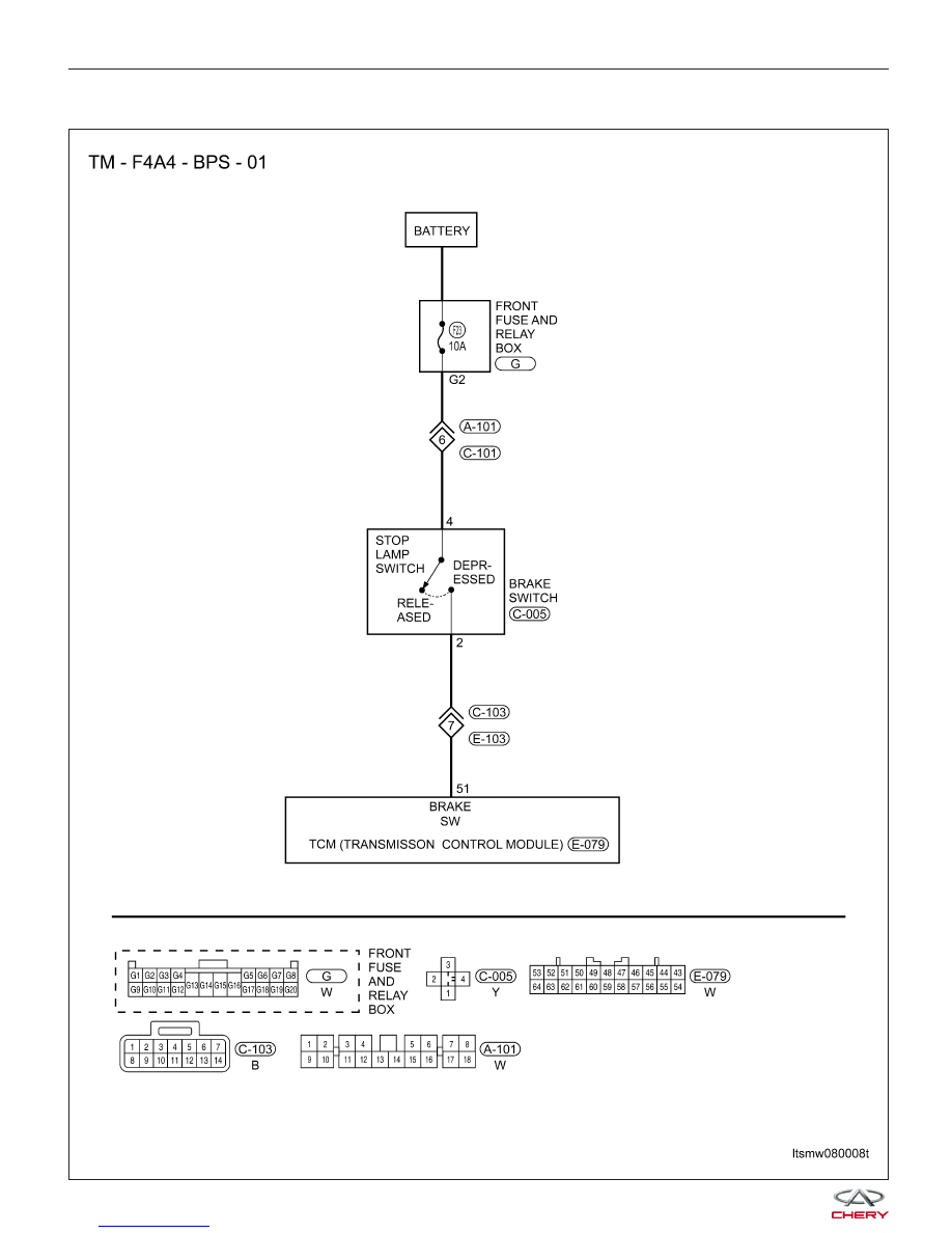
26 - Brake Pedal Position Switch Circuit Malfunction

DIAGNOSIS & TESTING

LTSMW080008T


On Board Diagnostic Logic
• Self-diagnosis detection logic.

DTC NO.

DTC DEFINITION

DTC DETECTION

CONDITION

DTC SET

CONDITION

POSSIBLE CAUSES

26

Brake pedal position

switch circuit

malfunction

Vehicle is driving

The brake switch is

on while vehicle is

driving

• Brake switch

• Harness or
connectors (The
sensor circuit is open
or shorted)

• TCM

DTC Confirmation Procedure:

Before performing the following procedure, confirm that battery voltage is more than 12 V.

• Connect the X-431 scan tool to the Data Link Connector (DLC) - use the most current software available.

• After connection, press POWER key to start X-431.

• Turn ignition switch on, with the scan tool, view and erase stored DTCs in the TCM.

• Start engine then select ⬙D⬙ position.

• Drive the vehicle.

• With the scan tool, select view DTC and data stream.

• If the DTC is detected, the DTC condition is current. Go to Diagnostic Procedure - Step 1.

• If the DTC is not detected, the DTC condition is intermittent (See Diagnostic Help and Intermittent DTC Trou-

bleshooting in Section 08 Transaxle & Transfer Case for more information).

NOTE :
While performing electrical diagnosis & testing, always refer to the electrical schematics for specific circuit
and component information.

Diagnostic Procedure

1.

CHECK BRAKE PEDAL POSITION SWITCH SIGNAL

• With the scan tool, select view DTC and data stream for A/T.

• Start vehicle and read out the value of ⬙STOP LAMP SWITCH⬙.

ITEM

CONDITION

DISPLAY

VALUE

Stop lamp switch

During driving

OFF

Is the check result normal?

Yes

>>

The condition that caused this DTC is intermittent (See Diagnostic Help in Section 08 Transaxle &

Transfer Case).

No

>>

Go to the next step.

DIAGNOSIS & TESTING

08


2.

CHECK BRAKE SWITCH POWER SUPPLY

• Stop vehicle.

• Check sensor power supply between sensor terminal 3 and ground in the sensor electrical connector C-005.

BRAKE SWITCH

CONDITION

VALUE (VOLT)

Depress brake switch

Battery voltage

Release brake switch

0

Is the check result normal?

Yes

>>

Go to the next step.

No

>>

Replace the brake switch.

3.

DETECT MALFUNCTIONING PART

• Check the following:

− Harness connectors A-102, E-105
− Harness for a short between TCM and brake switch

Is the check result normal?

Yes

>>

Go to the next step.

No

>>

Repair or replace short to power in harness or connectors.

4.

CHECK DTC

• With the X-431 scan tool, read TCM DTCs.

• Refer to ⬙DTC Confirmation Procedure⬙.

Is DTC 26 still present?

Yes

>>

Replace the TCM.

No

>>

The system is now operating properly.
Reassemble the vehicle and road test to verify the customers complaint is repaired.

DIAGNOSIS & TESTING


31 - Reverse/Low Solenoid Malfunction

DIAGNOSIS & TESTING

LTSMW080005T

08


Content   ..  278  279  280  281   ..