Chery Tiggo. Manual - part 278


  Index      Chery     Chery Tiggo - service repair manual 2009 year


Search            


Content   ..  276  277  278  279   ..


Chery Tiggo. Manual - part 278


3.

DETECT MALFUNCTIONING PART

• Check the following:

− Harness connectors A-102, E-105
− Body fuse and relay box H13
− Fuse 3 (10A)
− Harness open or short between input shaft speed sensor and fuse

Is the check result normal?

Yes

>>

Go to the next step.

No

>>

Repair or replace the open circuit or short to ground or short to power in harness or connectors.

4.

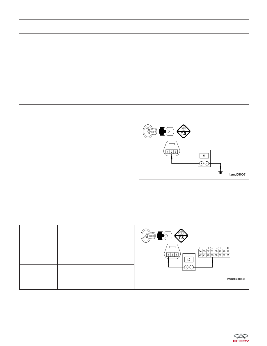
CHECK INPUT SHAFT SPEED SENSOR SIGNAL CIRCUIT

• Check sensor signal circuit between sensor terminal 2 and ground in the sensor electrical connector E-088.

• 5 V should exist.

Is the check result normal?

Yes

>>

Go to the next step.

No

>>

Repair or replace open circuit or short to

power or short to ground.

5.

CHECK INPUT SHAFT SPEED SENSOR GROUND CIRCUIT

• Turn the ignition switch off.

• Disconnect TCM connector.

• Check for harness continuity between the following terminals:

INPUT SPEED

SENSOR

CONNECTOR

TERMINAL

TCM

CONNECTOR

TERMINAL

CONTINUITY

1

39

Yes

• Check the harness for short to power and short to ground.

Is the check result normal?

Yes

>>

Go to the next step.

No

>>

Repair or replace open circuit or short to power or short to ground.

DIAGNOSIS & TESTING

LTSMD080061


6.

CHECK INPUT SHAFT SPEED SENSOR SIGNAL

• Connect the TCM and sensor electrical connector.

• Start the vehicle and perform the following:

− Engine: 2000 RPM
− Vehicle: 50 km/h
− Gear: 3

• Check sensor signal between sensor terminal 2 and ground in the sensor electrical connector E-088 with the

X-431 or oscilloscope.

• Make sure the wave shape is normal and signal voltage is fluctuating from 0 - 5 V.

Is the check result normal?

Yes

>>

Go to step 9.

No

>>

Go to the next step.

7.

CHECK INPUT SHAFT SPEED SENSOR

• Perform the following:

− Loosen the bolt of the sensor.
− Remove the sensor.
− Visually inspect the sensor for missing or chipped teeth.

Is the check result normal?

Yes

>>

Replace the input speed sensor.
Monitor the input speed sensor signal on the X-431 or oscilloscope.
− If the input speed sensor signals were normal, the system is OK.
− If the input speed sensor signals were still irregular or missing, go to step 8.

No

>>

Replace input speed sensor.

8.

CHECK THE RETAINER OF DECELERATION CLUTCH

• Disassemble and inspect the A/T and replace the retainer for the deceleration clutch.

• Check for a chipped and damaged signal retainer for the deceleration clutch.

Is the check result normal?

Yes

>>

Go to the next step.

No

>>

Replace the retainer for the deceleration clutch.
Monitor the input speed sensor signal on the X-431 or oscilloscope.
If the signal pulse is not normal, repair the noise interference.

9.

CHECK DTC

• With the X-431 scan tool, read TCM DTCs.

• Refer to ⬙DTC Confirmation Procedure⬙.

Is the check result normal?

Yes

>>

The system is now operating properly.
Reassemble the vehicle and road test to verify the customers complaint is repaired.

No

>>

Replace the TCM.

DIAGNOSIS & TESTING

08


23 - Output Speed Sensor Fault

DIAGNOSIS & TESTING

LTSMW080007T


On Board Diagnostic Logic
• Self-diagnosis detection logic.

DTC NO.

DTC DEFINITION

DTC DETECTION

CONDITION

DTC SET

CONDITION

POSSIBLE CAUSE

23

Output speed

sensor

Vehicle is driving

• The Transaxle
Control Module
(TCM) will set this
DTC when the TCM
didn’t received pulse
signal from the
output shaft speed
sensor for above 1
seconds when the
vehicle is driving for
30 km/h at 3 or 4
gear.

• If the DTC was
set for 4 times, then
the A/T will be
locked in 3rd gear
(D gear) or shifted
to low gear when in
sports mode.

• Output shaft speed
sensor

• Harness or
connectors (The
sensor circuit is open
or shorted)

• Transfer case
driven and drive gear

• TCM

DTC Confirmation Procedure:

Before performing the following procedure, confirm that battery voltage is more than 12 V.

• Turn ignition switch off.

• Connect the X-431 scan tool to the Data Link Connector (DLC) - use the most current software available.

• Turn ignition switch on, with the scan tool, view and erase stored DTCs in the TCM.

• Start engine and warm it to normal operating temperature, then select ⬙D⬙ position.

• Drive the vehicle up to 30 km/h or more at 3 or 4 gear.

• Driving the vehicle uphill will help maintain the driving conditions required for this test.

• With the scan tool, select view DTC and data stream.

• If the DTC is detected, the DTC condition is current. Go to Diagnostic Procedure - Step 1.

• If the DTC is not detected, the DTC condition is intermittent (See Diagnostic Help and Intermittent DTC Trou-

bleshooting in Section 08 Transaxle & Transfer Case for more information).

NOTE :
While performing electrical diagnosis & testing, always refer to the electrical schematics for specific circuit
and component information.

DIAGNOSIS & TESTING

08


Content   ..  276  277  278  279   ..