Chery Tiggo. Manual - part 255


  Index      Chery     Chery Tiggo - service repair manual 2009 year


Search            


Content   ..  253  254  255  256   ..


Chery Tiggo. Manual - part 255


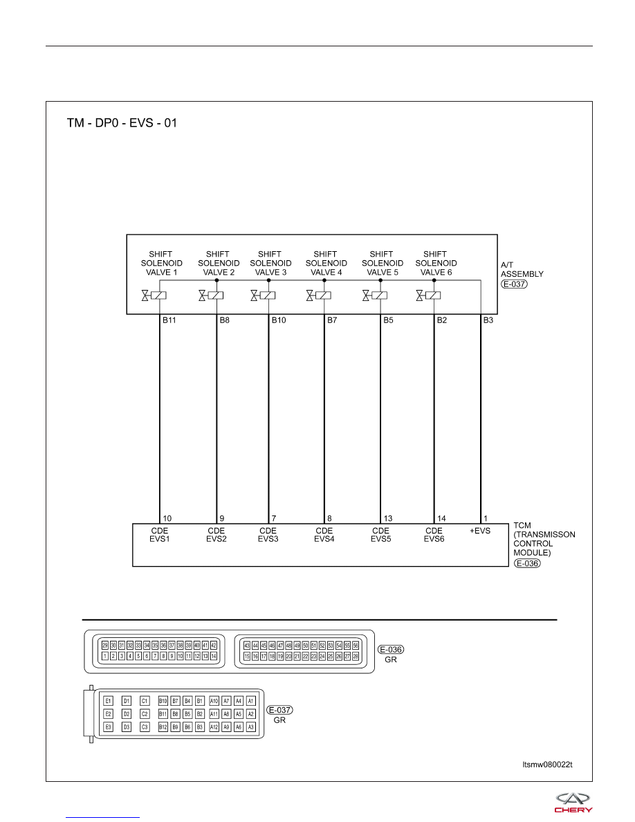
P0768 - Shift Solenoid Valve 4 (SSV4) Short To Power Supply
P0768 - Shift Solenoid Valve 4 (SSV4) Open Or Short To Ground Circuit

DIAGNOSIS & TESTING

LTSMW080022T


On Board Diagnostic Logic
• Self-diagnosis detection logic.

DTC NO.

DTC

DEFINITION

DTC

DETECTION

CONDITION

DTC SET CONDITION

POSSIBLE

CAUSES

P0768

Shift Solenoid

Valve 4 (SSV4)

short to power

supply

Vehicle is driving

The Transaxle Control Module
(TCM) will set this DTC when the
TCM detected an improper voltage
drop when it tries to operate the
solenoid valve.

• Shift Solenoid
Valve 4 (SSV4)

• Harness or
connectors (The
sensor circuit
short to power
supply)

• Transaxle
Control Module
(TCM)

P0768

Shift Solenoid

Valve 4 (SSV4)

open or short to

ground circuit

Vehicle is driving

The Transaxle Control Module

(TCM) will set this DTC when the
TCM detected an improper voltage
drop when it tries to operate the
solenoid valve.

• Shift Solenoid
Valve 4 (SSV4)

• Harness or
connectors (The
sensor circuit is
open or shorted)

• Transaxle
Control Module
(TCM)

DTC Confirmation Procedure:

Before performing the following procedure, confirm that battery voltage is more than 12 V.

• Turn ignition switch off.

• Connect the X-431 scan tool to the Data Link Connector (DLC) - use the most current software available.

• Turn ignition switch on.

• With the scan tool, record and erase stored DTCs in the TCM.

• Start engine and warm it to normal operating temperature.

• With the scan tool, select view DTC and data stream.

• If the DTC is detected, the DTC condition is current. Go to Diagnostic Procedure - Step 1.

• If the DTC is not detected, the DTC condition is intermittent (See Diagnostic Help and Intermittent DTC Trou-

bleshooting in Section 08 Transaxle & Transfer Case for more information).

• If using the appropriate diagnostic test tool, you can diagnose the TCM harness while the TCM is still con-

nected.

• Using the appropriate diagnostic test tool in this way will help prevent electrical connector terminal damage.

NOTE :
While performing electrical diagnosis & testing, always refer to the electrical schematics for specific circuit
and component information.

DIAGNOSIS & TESTING

08


Diagnostic Procedure

1.

CHECK A/T SOLENOID SIGNAL

• With the scan tool, select view DTC and data stream for A/T.

• Start the engine.

• Monitor the value of the gear position as indicated in the following table while driving:

SEQUENCE SOLENOID (EVS) CONDITION

LEVER

POSITION

EVS

EVS1

EVS2

EVS3

EVS4

EVS5

EVS6

R

Not

active

Not

active

Not

active

Not

active

Not

active

Not

active

N/P

Not

active

Not

active

Active

Not

active

Not

active

Not

active

1

Not

active

Not

active

Active

Active

Not

active

Not

active

2

Not

active

Active

Not

active

Active

Not

active

Not

active

3

Not

active

Not

active

Not

active

Not

active

Not

active

Not

active

4

Active

Active

Not

active

Not

active

Not

active

Not

active

Is the check result normal?

Yes

>>

The condition that caused this DTC is intermittent (See Diagnostic Help in Section 08 Transaxle &

Transfer Case).

No

>>

Go to the next step.

2.

ACTUATE TEST

• With X-431, perform the solenoid actuate test.

• The solenoid should be heard.

Is the check result normal?

Yes

>>

Go to step 6.

No

>>

Go to the next step.

DIAGNOSIS & TESTING


3.

CHECK SHIFT SOLENOID VALVE 4 (SSV4) RESISTANCE

• Check SSV4 resistance as follows:

NUMBER

SOLENOID

1

Shift Solenoid Valve 1

2

Shift Solenoid Valve 2

3

Shift Solenoid Valve 3

4

Shift Solenoid Valve 4

5

Shift Solenoid Valve 5

6

Shift Solenoid Valve 6

7

Pressure adjust solenoid

valve

8

Torque converter lock

solenoid valve

9

Manual valve

10

Valve body

• Check SSV4 resistance as shown in the following table:

SHIFT SOLENOID VALVE

A/T ASSEMBLY

TERMINAL

VALVE 1 (SSV1)

B11 - B3

VALVE 2 (SSV2)

B8 - B3

VALVE 3 (SSV3)

B10 - B3

VALVE 4 (SSV4)

B7 - B3

VALVE 5 (SSV5)

B5 - B3

VALVE 6 (SSV6)

B2 - B3

RESISTANCE (23°C)

38 - 42 (

⍀)

Is the check result normal?

Yes

>>

Replace the valve with a known good one.
With X-431, perform the solenoid actuate test.
− If the solenoid can be heard, go to step 6.
− If the solenoid can’t be heard, go to the next step.

No

>>

Replace the damaged solenoid valve.

DIAGNOSIS & TESTING

08


Content   ..  253  254  255  256   ..