Chery Tiggo. Manual - part 243
4.
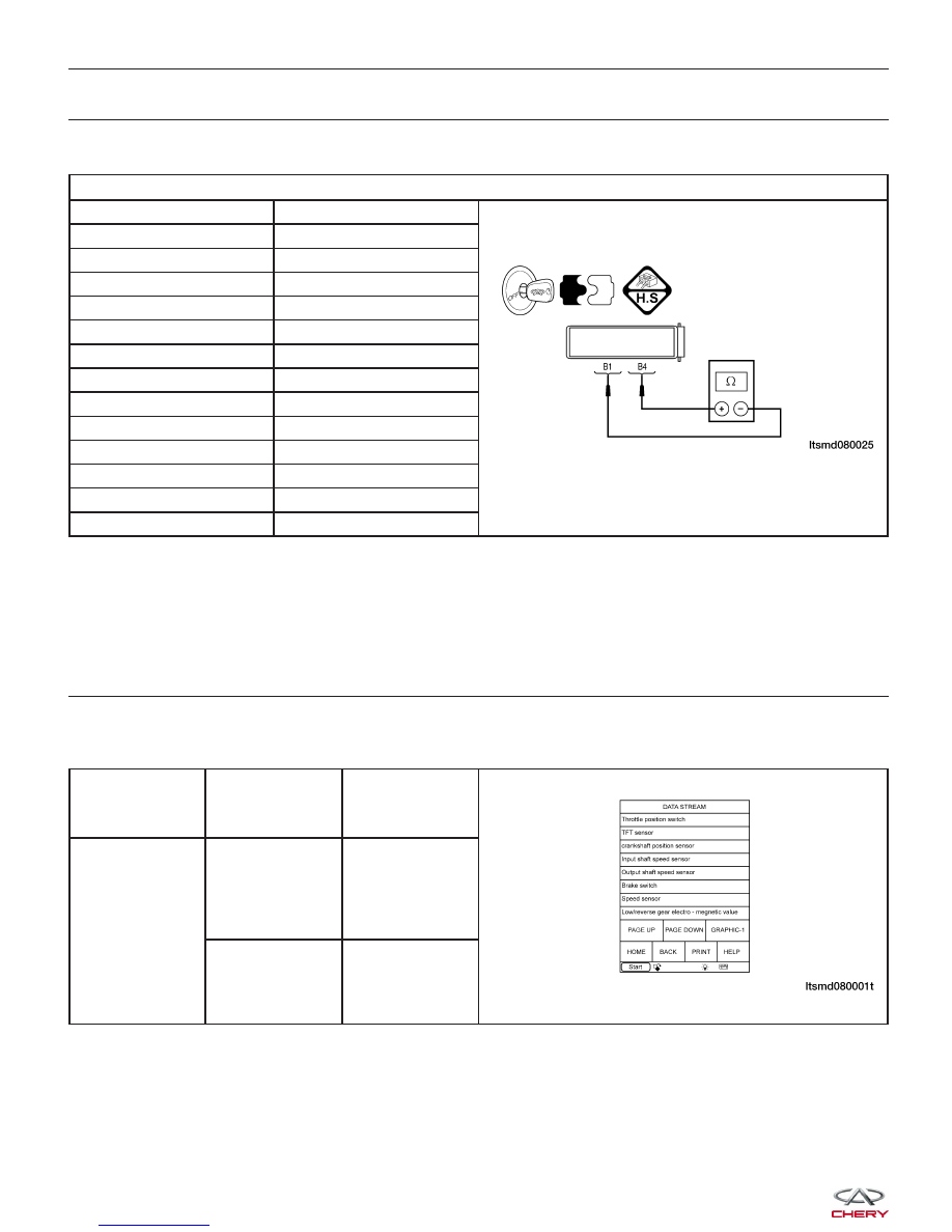
CHECK TFT SENSOR
• Check TFT sensor as follows:
TFT SENSOR RESISTANCE
TEMPERATURE °C
RESISTANCE
⍀
-50
93917
-30
28237.4
-10
9826
0
6079
20
2528.5
25
2063
40
1159.2
50
810.4
70
419.1
80
309.2
100
176.2
120
105.9
140
66.7
Is the check result normal?
Yes
>>
Go to the next step.
No
>>
Replace the TFT sensor.
5.
CHECK A/T FLUID PRESSURE SENSOR
• Turn ignition switch on.
• With X-431 scan tool, select view TCM data stream and compare to the following table.
ITEM
CONDITION
DISPLAY
VALUE
Fluid Pressure
• Ignition switch:
ON
• Engine: Not
running
Below 0.2 bar
• Engine: Idle
• TFT: 31°C
• ECT: 30°C
Approximately
0.05 bar
Is the check result normal?
Yes
>>
Go to the next step.
No
>>
Replace the TCM.
DIAGNOSIS & TESTING