Chery Tiggo. Manual - part 219


  Index      Chery     Chery Tiggo - service repair manual 2009 year


Search            


Content   ..  217  218  219  220   ..


Chery Tiggo. Manual - part 219


Removal & Installation

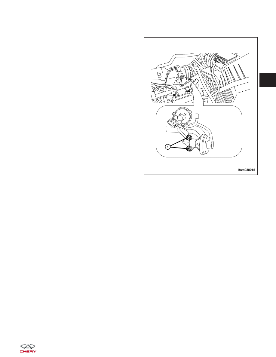
1. Remove the EGR vacuum hose.

2. Remove the EGR valve retaining bolts (1).

(Tighten: EGR valve retaining bolts to 25 N·m)

3. Installation is in the reverse order of removal.

ON-VEHICLE SERVICE

LTSM030015

03


FUEL DELIVERY

04

CONTENTS

page

Fuel Delivery System . . . . . . . . . . . . . . . . . . . . . . . . . . . . . . . . . . . . . . . . . . . . . . . . . . . . . . . . . . . . . . . . . 04-1

FUEL DELIVERY SYSTEM

GENERAL INFORMATION

04-2

Description

04-2

Operation

04-4

Specifications

04-4

Special Tools

04-5

Electrical Schematics

04-6

DIAGNOSIS & TESTING

04-12

Fuel Pressure Test

04-12

ON-VEHICLE SERVICE

04-15

Fuel Pressure Relief Procedure

04-15

Description

04-15

Fuel Pump

04-15

Description

04-15

Operation

04-15

Removal & Installation

04-15

Fuel Pump Inspection

04-17

Fuel Filter

04-18

Description

04-18

Operation

04-18

Removal & Installation

04-18

Fuel Injector Rail

04-19

Description

04-19

Operation

04-19

Removal & Installation - 1.6L & 1.8L &
2.0L

04-19

Removal & Installation - 2.4L

04-20

Fuel Injector

04-20

Description

04-20

Operation

04-20

Removal & Installation - 1.6L & 1.8L &
2.0L

04-20

Removal & Installation - 2.4L

04-21

Fuel Injector Inspection

04-22

Fuel Pressure Regulator - With
Mitsubishi 2.4L Engine

04-23

Description

04-23

Operation

04-23

Removal & Installation

04-23

Fuel Pressure Regulator Inspection

04-24

04


GENERAL INFORMATION

Description

The fuel system consists of a fuel tank with a reservoir, fuel pump, fuel filter, fuel delivery line, fuel rail, fuel rail pulse
damper and fuel injectors. The Engine Control Module (ECM) controls the fuel system based on signal inputs. The
immobilizer module signals the ECM to activate the fuel system. If the ECM does not receive the proper signal from
the immobilizer module, the ECM will not allow the fuel system to operate.

• The ACTECO engine utilizes a returnless fuel delivery system.

• The MITSUBISHI engine utilizes a fuel return fuel delivery system.

WARNING!

Do not smoke or carry lighted tobacco or open flame of any type when working on or near any fuel-related
component. Highly flammable mixtures are always present and may be ignited. Failure to follow these instruc-
tions may result in serious personal injury.

Fuel Filler Assembly

1 - Fuel Filler Cap Assembly

2 - Fuel Filler Shield

3 - Fuel Filler Tube Assembly

4 - Bolt

5 - Hose Clamp

6 - Fuel Filler Hose

7 - Fuel Filler Air Hose

8 - Fuel Tank Assembly

9 - Electric Fuel Pump Assembly

10 - Fuel Delivery Pipe Assembly

11 - Fuel Return Pipe Assembly

12 - Hose Clamp

13 - Bolt

LTSM040008


Fuel Tank Assembly

1 - Fuel Tank Band I

2 - Fuel Tank Band II

3 - Fuel Tank Band III

4 - Fuel Tank Protector

5 - Fuel Tank Assembly

6 - EVAP Hose

7 - Fuel Delivery And Return Pipes Assembly

8 - Fuel Filter Bracket

9 - Fuel Filter Assembly

10 - Bolt

11 - Fuel Delivery Pipe

12 - Electric Fuel Pump Assembly

13 - Bolt

GENERAL INFORMATION

LTSM040009

04


Content   ..  217  218  219  220   ..