Chery Tiggo. Manual - part 206


  Index      Chery     Chery Tiggo - service repair manual 2009 year


Search            


Content   ..  204  205  206  207   ..


Chery Tiggo. Manual - part 206


Air Flow Sensor

Description

The air flow sensor is placed in the air intake hose. The air flow sensor measures the intake flow rate by measuring
a part of the entire intake flow. The air flow sensor converts the amount of air drawn into the engine into a voltage
signal. The Engine Control Module (ECM) needs to know intake air volume to calculate engine load. This is neces-
sary to determine how much fuel to inject.

Operation

The air flow sensor controls the temperature of the hot wire to a certain amount. The heat generated by the hot wire
is reduced as the intake air flows around it. The more air, the greater the heat loss. Therefore, the electric current
supplied to the hot wire is changed to maintain the temperature of the hot wire as air flow increases. The ECM
detects the air flow by means of this voltage signal change.

Removal & Installation

1. Disconnect the negative battery cable.

2. Disconnect air flow sensor electrical connector

from the wiring harness connector.

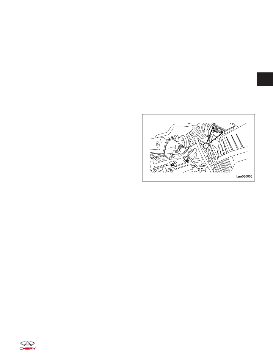
3. Remove the air flow sensor retaining bolts (1).

(Tighten: Air flow sensor retaining bolt to 8 N·m)

4. Remove the air flow sensor.

5. Installation is in the reverse order of removal.

ON-VEHICLE SERVICE

LTSM030006

03


Throttle Control Actuator

Description

The throttle body is located on the intake manifold. The throttle body meters air into the intake manifold.

Throttle control actuator consists of throttle control valve, throttle position sensor, idle air control motor, etc.

Operation

Filtered air from the air cleaner enters the intake manifold through the throttle body. A throttle valve (plate) is used to
supply air for idle and driving conditions. The throttle position sensor is part the throttle body. The throttle position
sensor signal is used by the ECM to determine throttle position. The ECM controls the throttle control to meter air
into the engine. This regulates engine power. The vehicle is in sense a “Drive by Wire” system.

Removal & Installation

1. Remove the engine cover.

2. Disconnect the negative battery cable.

3. Disconnect the throttle position sensor and idle air control motor electrical connect on the throttle control actua-

tor.

4. Remove the accelerator cable on the throttle control actuator.

5. Remove three hoses on the throttle control actuator.

6. Remove four throttle control actuator mounting

bolts (1).
(Tighten: Throttle control actuator bolts to 10 N·m)

7. Remove the throttle control actuator and gasket carefully.

8. Installation is in the reverse order of removal.

NOTE :
Replace a new throttle control actuator gasket when installing.

ON-VEHICLE SERVICE

LTSM030010


Engine Control Module (ECM)

Description

The Engine Control Module (ECM) for this model is serviced only as a complete unit.

Operation

The ECM is a pre-programmed, microprocessor-based digital computer. It regulates ignition timing, air-fuel ratio,
emission control devices, charging system, certain transmission features, speed control, air conditioning compressor
clutch engagement and idle speed. The ECM can adapt its programming to meet changing operating conditions.

Removal & Installation

1. Disconnect the negative battery cable.

2. Remove the glove box (See Instrument Panel Removal & Installation in Section 15 Body & Accessories).

3. Disconnect the ECM connector.

4. Remove the ECM retaining bolts (1).

(Tighten: ECM retaining bolts to 10 N·m)

5. Remove the ECM.

6. Installation is in the reverse order of removal.

ON-VEHICLE SERVICE

LTSM030025

03


Throttle Position Sensor (TPS)

Description

The 4-wire throttle position sensor (TPS) is mounted on the throttle body and is connected to the throttle valve.

Operation

The TPS is a 4-wire variable resistor that provides the Engine Control Module (ECM) with an input signal that rep-
resents the throttle valve position of the throttle body. The sensor is connected to the throttle valve shaft. As the
position of the throttle valve changes, the resistance (output voltage) of the TPS changes.

Removal & Installation

1. Disconnect the negative battery cable.

2. Disconnect throttle position sensor electrical con-

nector clamp from the wiring harness connector.

3. Remove the throttle position sensor retaining bolts

(1).

4. Remove the throttle position sensor.

5. Installation is in the reverse order of removal.

ON-VEHICLE SERVICE

LTSM030027


Content   ..  204  205  206  207   ..