Chery Tiggo. Manual - part 203


  Index      Chery     Chery Tiggo - service repair manual 2009 year


Search            


Content   ..  201  202  203  204   ..


Chery Tiggo. Manual - part 203


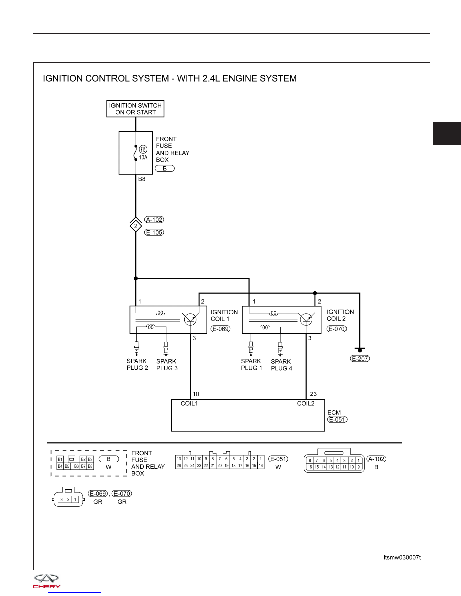
44 - Ignition Signal

DIAGNOSIS & TESTING

LTSMW030007T

03


Check reference values between ECM terminals and ground under the following conditions:

ECM TERMINAL NO.

ITEM

CONDITION

DATA (DC VOLTAGE)

10

Ignition coil 1

Engine: 3000 RPM

0.3 - 3.0 V

23

Ignition coil 2

0.3 - 3.0 V

On Board Diagnostic Logic
• Self-diagnosis detection logic.

DTC NO.

DTC DEFINITION

DTC DETECTION

CONDITION

DTC SET

CONDITION

POSSIBLE CAUSE

44

Ignition signal

• Engine speed: 50
- 4000 RPM

• Except decelerate
and accelerate
suddenly or
decelerate suddenly

The misfire times of
No.1 and No.4 or
No.2 and No.3 is
more than the reset
misfire times of per
1000 RPM.

• Ignition coil

• Ignition primary
harness or
connectors

• Spark plug and
tension cable

• Cylinder pressure

• ECM

DTC Confirmation Procedure:

Before performing the following procedure, confirm that battery voltage is more than 12 V.

• Turn ignition switch off.

• Connect the X-431 scan tool to the Data Link Connector (DLC) - use the most current software available.

• Turn ignition switch on.

• With the scan tool, record and erase stored DTCs in the ECM.

• Start engine and warm it to normal operating temperature then select view DTC.

• If DTC is detected, go to Diagnostic Procedure - Step 1.

• If the DTC is not detected, the DTC condition is intermittent (See Diagnosis & Testing Diagnostic Help in Sec-

tion 03 Electronic Engine Controls).

NOTE :
Before performing the following procedure, make sure that the ECM ground connection is in good condition.

NOTE :
While performing electrical diagnosis & testing, always refer to the electrical schematics for specific circuit
and component information.

Diagnostic Procedure

1.

CHECK GROUND CONNECTION

• Turn ignition switch off.

• Loosen and retighten ground screws on the body (See Ground Inspection in Section 03 Electronic Engine Con-

trols).

• Inspect the ground connections E-207 and E-208 (See Vehicle Wiring Harness Layout - Engine Room Harness

(With Mitsubishi 2.4L Engine) in Section 16 Wiring).

Is the ground connections OK?

Yes

>>

Go to the next step.

No

>>

Repair or replace ground connection.

DIAGNOSIS & TESTING


2.

CHECK ENGINE START

• Start the engine.

Is any cylinder ignited?

Yes

>>

If with the X-431, go to the next step.
If without the X-431, go to step 3.

No

>>

Go to step 4.

3.

PERFORM ACTIVE TEST FUNCTION

• Select ⬙ACTIVE TEST⬙ menu.

• Perform ignition active test (If the X-431 has the function).

• Make sure that each test produces a momentary engine speed drop.

Is the check result normal?

Yes

>>

Inspection end.

No

>>

Go to step 4.

4.

CHECK FUNCTION OF IGNITION

• Let engine run at 3000 RPM.

• Read voltage signal between ECM terminals 10, 23 and ground.

IGNITION

COIL

TERMINAL

NO.

ITEM

CONDITION

DATA (DC

VOLTAGE)

10

Ignition coil

1 terminal 3

Engine:

3000 RPM

0.3 - 3.0 V

23

Ignition coil

2 terminal 3

0.3 - 3.0 V

• If with check tool-timing mark lamp, check the actual ignition time.

CHECK ITEM

CONTENT

NORMAL VALUE

Ignition coil with power

transistor

• Engine: Warm-up
condition

• Timing lamp (For check
the actual ignition time)

Engine: Idle

2 - 18° BTDC

Engine: 2500 RPM

18 - 38° BTDC

Is the check result normal?

Yes

>>

Go to step 10.

No

>>

Go to the next step.

DIAGNOSIS & TESTING

03


5.

CHECK IGNITION COIL ELECTRICAL CONNECTOR

• Turn ignition switch off.

• Disconnect the ignition coil electrical connector (1).

• Inspect the electrical connector for damage.

Is the electrical connector OK?

Yes

>>

Go to the next step.

No

>>

Repair or replace the electrical connector

as necessary.

6.

CHECK IGNITION COIL POWER SUPPLY CIRCUIT FOR AN OPEN OR SHORT

• Turn ignition switch on.

• Check supply voltage between ignition coil terminal

1 and ground in the ignition coil electrical connec-
tor.

• Battery voltage should exist.

Is the check result normal?

Yes

>>

Go to step 8.

No

>>

Go to the next step.

7.

DETECT MALFUNCTIONING PART

• Check the following:

− Fuse 15
− Front fuse and relay box B8
− Harness connectors A-102, E-105
− Harness open or short between ignition coil and fuse

Is the check result normal?

Yes

>>

Go to the next step.

No

>>

Repair or replace malfunctioning parts.

DIAGNOSIS & TESTING

LTSM030017

LTSMD030022


Content   ..  201  202  203  204   ..