Chery Tiggo. Manual - part 201


  Index      Chery     Chery Tiggo - service repair manual 2009 year


Search            


Content   ..  199  200  201  202   ..


Chery Tiggo. Manual - part 201


2.

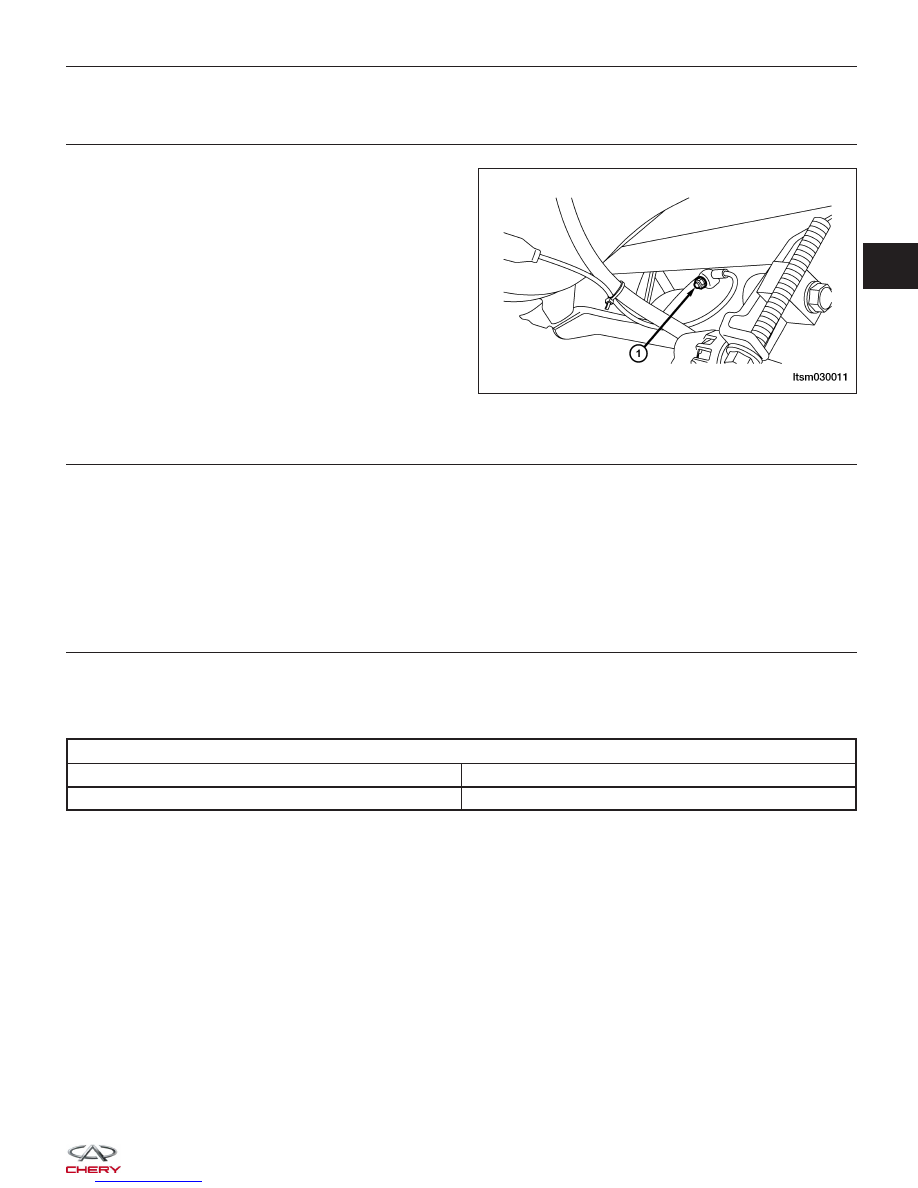
CHECK KNOCK SENSOR ELECTRICAL CONNECTOR

• Disconnect the knock sensor electrical connector

E-066 (1).

• Inspect the electrical connector for damage.

Is the electrical connector OK?

Yes

>>

Go to the next step.

No

>>

Repair or replace the electrical connector

as necessary.

3.

CHECK THE KNOCK SENSOR GROUND CIRCUIT

• Check continuity between knock sensor terminal 1 and ground.

• Continuity should exist.

Is the check result normal?

Yes

>>

Go to the next step.

No

>>

Repair or replace the knock sensor ground circuit.

4.

CHECK KNOCK SENSOR SIGNAL CIRCUIT

• Disconnect ECM harness connector.

• Check harness continuity between sensor connector E-066, terminal 1 and ground, sensor terminal 2 and ECM

terminal 62.

CHECK SENSOR CIRCUIT

ECM TERMINAL

KNOCK SENSOR TERMINAL

62

2

• Also check harness for short to power and short to ground.

Is the check result normal?

Yes

>>

Go to the next step.

No

>>

Repair circuit for an open or short in harness or connectors.

DIAGNOSIS & TESTING

LTSM030011

03


5.

CHECK KNOCK SENSOR SIGNAL

• Connect knock sensor (1) connector.

• Set multimeter to voltage range.

• Check knock sensor (1) output signal as table

shown.

CHECK OUTPUT SIGNAL

KNOCK SENSOR TERMINAL NO.

TEST METHOD

DATA (AVERAGE DC VOLTAGE)

1 & 2

• Test Method 1: Knock at cylinder
with rubber hammer.

Output signal voltage should exist.

• Test Method 2: Knock at sensor
slightly.

• Output signal voltage should exist.

Is the check result normal?

Yes

>>

Go to the next step.

No

>>

Replace knock sensor.

6.

CHECK DTC

• With the X-431 scan tool, read ECM DTCs.

• Refer to ⬙DTC Confirmation Procedure⬙.

Is DTC 31 still present?

Yes

>>

Replace the ECM.

No

>>

The system is now operating properly.
Reassemble the vehicle and road test to verify the customers complaint is repaired.

DIAGNOSIS & TESTING

LTSM030011


41 - Injector

DIAGNOSIS & TESTING

LTSMW030008T

03


Check reference values between ECM terminals and ground under the following conditions:

ECM TERMINAL NO.

ITEM

CONDITION

DATA (DC VOLTAGE)

1

Injector 1

• Engine is running

• Warm-up condition

• Accelerate suddenly

Voltage: 11 - 14 V

2

Injector 3

14

Injector 2

15

Injector 4

On Board Diagnostic Logic
• Self-diagnosis detection logic.

DTC NO.

DTC DEFINITION

DTC DETECTION

CONDITION

POSSIBLE CAUSE

41

Injector

Engine is running

• Injector

• Harness or connectors

• ECM

DTC Confirmation Procedure:

Before performing the following procedure, confirm that battery voltage is more than 12 V.

• Turn ignition switch off.

• Connect the X-431 scan tool to the Data Link Connector (DLC) - use the most current software available.

• Turn ignition switch on.

• With the scan tool, record and erase stored DTCs in the ECM.

• Start engine and warm it to normal operating temperature then select view DTC.

• If DTC is detected, go to Diagnostic Procedure - Step 1.

• If the DTC is not detected, the DTC condition is intermittent (See Diagnosis & Testing Diagnostic Help in Sec-

tion 03 Electronic Engine Controls).

NOTE :
Before performing the following procedure, make sure that the ECM ground connection is in good condition.

NOTE :
While performing electrical diagnosis & testing, always refer to the electrical schematics for specific circuit
and component information.

Diagnostic Procedure

1.

CHECK GROUND CONNECTION

• Turn ignition switch off.

• Loosen and retighten ground screws on the body (See Ground Inspection in Section 03 Electronic Engine Con-

trols).

• Inspect the ground connection E-208 (See Vehicle Wiring Harness Layout - Engine Room Harness (With Mit-

subishi 2.4L Engine) in Section 16 Wiring).

Is the ground connections OK?

Yes

>>

Go to the next step.

No

>>

Repair or replace ground connection.

DIAGNOSIS & TESTING


Content   ..  199  200  201  202   ..