Chery Tiggo. Manual - part 197


  Index      Chery     Chery Tiggo - service repair manual 2009 year


Search            


Content   ..  195  196  197  198   ..


Chery Tiggo. Manual - part 197


5.

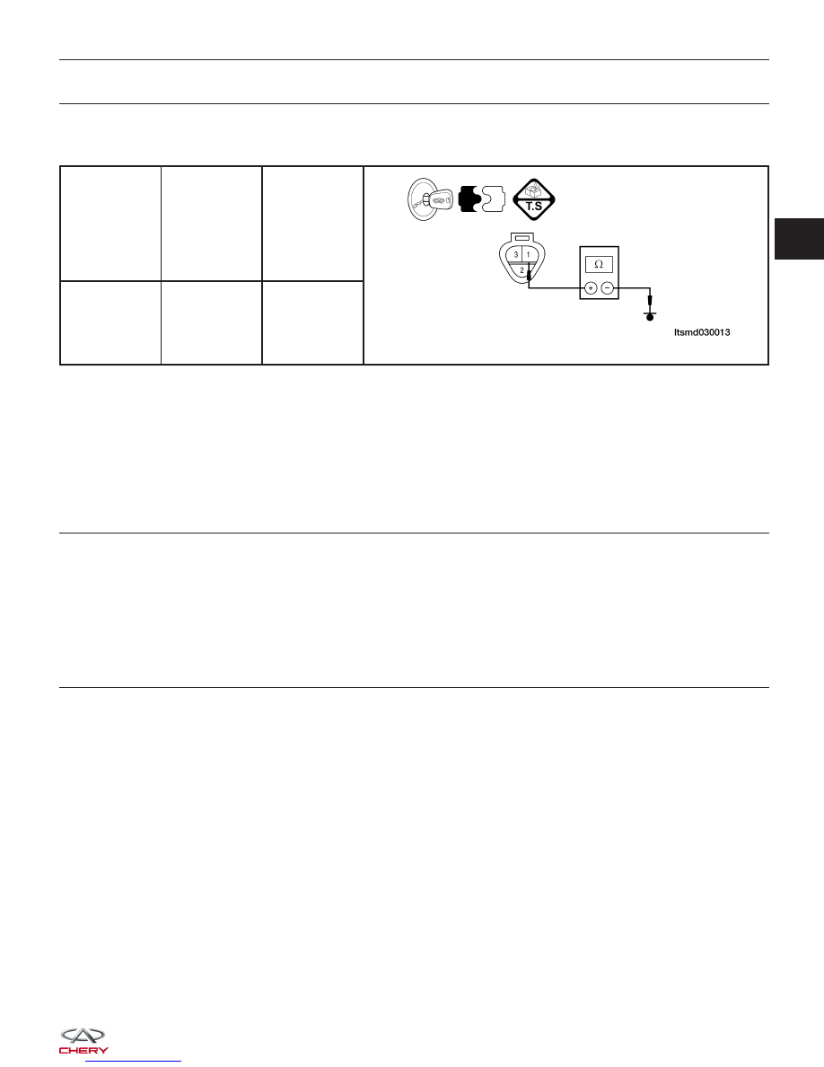
CHECK CKP SENSOR GROUND CIRCUIT FOR OPEN OR SHORT TO POWER

• Turn ignition switch off.

• Check harness continuity between following terminals.

CKP

SENSOR

TERMINAL

TERMINAL

CONTINUITY

1

Ground

Yes

• Continuity should exist.

• Also check harness for short to power.

Is the check result normal?

Yes

>>

Go to step 7.

No

>>

Go to the next step.

6.

DETECT MALFUNCTIONING PART

• Check harness for an open or short between CKP sensor and ground.

Is the check result normal?

Yes

>>

Go to the next step.

No

>>

Repair or replace harness or connectors.

7.

CHECK CKP SENSOR REFERENCE VOLTAGE

• Turn ignition switch on.

• Check voltage between CKP sensor terminal 2 and ground.

• 4.8 - 5.2 V should exist.

Is the check result normal?

Yes

>>

Go to step 9.

No

>>

Go to the next step.

DIAGNOSIS & TESTING

03


8.

CHECK CKP SENSOR INPUT SIGNAL CIRCUIT FOR AN OPEN OR SHORT

• Turn ignition switch off.

• Disconnect ECM connector.

• Check harness continuity between ECM terminal 73 and CKP sensor terminal 2.

• Continuity should exist.

• Also check harness for short to power and short to ground.

Is the check result normal?

Yes

>>

Replace the ECM.

No

>>

Repair circuit for an open or short circuit in harness or connectors.

9.

CHECK CKP SENSOR SIGNAL

• Turn ignition switch off.

• Connect ECM connector.

• Connect CKP sensor connector.

• Check sensor signal output.

TERMINAL NO.

ITEM

CONDITION

DATA (DC VOLTAGE)

73

Crankshaft Position (CKP)

sensor

• Ignition switch: ON

• Engine: Not cranking

4.8 - 5.2 V

• Engine: Cranking

0.4 - 4.0 V

• Engine: Idle

1.5 - 2.5 V

Is the check result normal?

Yes

>>

Go to step 12.

No

>>

Go to the next step.

10.

CHECK CKP SENSOR

• Check resistance as table shown:

− Remove the sensor.
− Visually check the sensor for chipping.
− Continuity should exist.

TERMINAL NO.

RESISTANCE

⍀ (25°C)

1 & 2

Except 0 or

1 & 3

2 & 3

Is the check result normal?

Yes

>>

Replace the CKP sensor with a known good CKP sensor.
Monitor the CKP sensor signal on the KES-200 screen.
− If the CKP sensor signals were normal, the system is OK.
− If the CKP sensor signals were still irregular or missing, go to step 11.

No

>>

Replace CKP sensor.

DIAGNOSIS & TESTING


11.

CHECK GEAR TOOTH

• Visually check for chipping signal plate gear tooth.

Is the check result normal?

Yes

>>

Go to the next step.

No

>>

Replace the signal plate.

12.

CHECK DTC

• With the X-431 scan tool, read ECM DTCs.

• Refer to ⬙DTC Confirmation Procedure⬙.

Is the check result normal?

Yes

>>

The system is now operating properly.
Reassemble the vehicle and road test to verify the customers complaint is repaired.

No

>>

Replace the ECM.

DIAGNOSIS & TESTING

03


23 - Camshaft Position Sensor

DIAGNOSIS & TESTING

LTSMW030011T


Content   ..  195  196  197  198   ..