Chery Tiggo. Manual - part 195


  Index      Chery     Chery Tiggo - service repair manual 2009 year


Search            


Content   ..  193  194  195  196   ..


Chery Tiggo. Manual - part 195


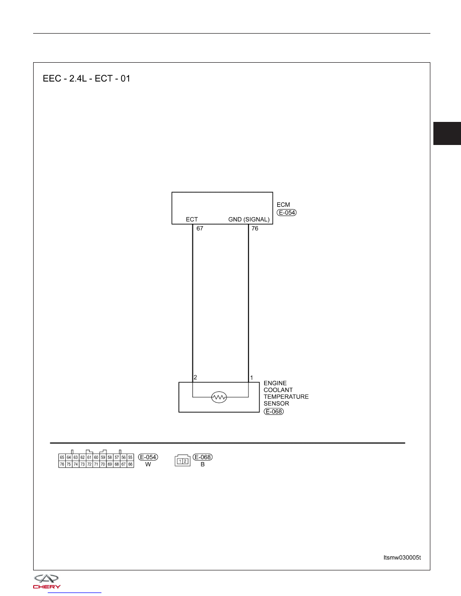
21 - Coolant Temperature Sensor

DIAGNOSIS & TESTING

LTSMW030005T

03


Check reference values between ECM terminals and ground under the following conditions:

ECM TERMINAL

NO.

ITEM

CONDITION

DATA (DC

VOLTAGE)

67

Engine Coolant

Temperature (ECT)

sensor

Ignition switch: ON

ECT: 0°C

3.2 - 3.8 V

ECT: 20°C

2.3 - 2.9 V

ECT: 40°C

1.3 - 1.9 V

ECT: 80°C

0.3 - 0.9 V

76

Sensor (GND)

-

Approximately 0 V

On Board Diagnostic Logic
• Self-diagnosis detection logic.

DTC NO.

DTC DEFINITION

DTC DETECTION

CONDITION

DTC SET

CONDITION

POSSIBLE CAUSE

21

Coolant temperature

sensor

• Ignition switch:
ON position for 60
seconds

• Engine: Running

• Signal output is
above 4.6 V for 4
seconds
continuously
(amount to -45°C
engine coolant
temperature).

• Signal output is
below 0.1 V for 4
seconds
continuously
(amount to 145°C
engine coolant
temperature).

• Engine Coolant
Temperature (ECT)
sensor

• Harness or
connectors

• ECM

• Ignition switch:
ON

• Engine speed is
above 500 RPM

• Signal output raise
from below 1.6 V to
above 1.6 V
(amount to 40°C
engine coolant
temperature).

• Signal output is
above 1.6 V for 5
minutes.

DTC Confirmation Procedure:

Before performing the following procedure, confirm that battery voltage is more than 12 V.

• Turn ignition switch off.

• Connect the X-431 scan tool to the Data Link Connector (DLC) - use the most current software available.

• Turn ignition switch on.

• With the scan tool, record and erase stored DTCs in the ECM.

• Start engine and warm it to normal operating temperature, then select view DTC and data stream.

• If the DTC is detected, the DTC condition is current. Go to Diagnostic Procedure - Step 1.

• If the DTC is not detected, the DTC condition is intermittent (See Diagnostic Help and Intermittent DTC Trou-

bleshooting in Section 03 Electronic Engine Controls for more information.

NOTE :
Before performing the following procedure, make sure that the ECM connection is in good condition.

NOTE :
While performing electrical diagnosis & testing, always refer to the electrical schematics for specific circuit
and component information.

DIAGNOSIS & TESTING


Diagnostic Procedure

1.

CHECK GROUND CONNECTION

• Turn ignition switch off.

• Loosen and retighten ground screws on the body (See Ground Inspection in Section 03 Electronic Engine Con-

trols).

• Inspect the ground connection E-208 (See Vehicle Wiring Harness Layout - Engine Room Harness (With Mit-

subishi 2.4L Engine) in Section 16 Wiring).

Is the ground connections OK?

Yes

>>

Go to the next step.

No

>>

Repair or replace ground connection.

2.

CHECK ENGINE COOLANT TEMPERATURE (ECT) SENSOR ELECTRICAL CONNECTOR

• Disconnect the ECT (1) electrical connector.

• Inspect the electrical connector for damage.

Is the electrical connector OK?

Yes

>>

Go to the next step.

No

>>

Repair or replace the electrical connector

as necessary.

DIAGNOSIS & TESTING

LTSM030007

03


3.

CHECK ENGINE COOLANT TEMPERATURE (ECT) SENSOR SIGNAL CIRCUIT FOR AN OPEN OR SHORT

• Turn ignition switch on.

• Check reference voltage between sensor terminal 2

and ground in the sensor electrical connector
E-068.

• 4.5 - 4.9 V should exist.

Is the check result normal?

Yes

>>

Go to step 5.

No

>>

Go to the next step.

4.

DETECT MALFUNCTIONING PART

• Turn ignition switch off.

• Disconnect ECM connector.

• Check harness for an open or short between ECT connector terminal 2 and ECM connector E-054, terminal 67.

Is the check result normal?

Yes

>>

Replace the ECM.

No

>>

Repair circuit for an open or short in harness or connectors.

5.

CHECK ECT SENSOR GROUND CIRCUIT FOR AN OPEN AND SHORT

• Check harness continuity between following terminals.

ECT SENSOR TERMINAL

ECM TERMINAL

1

76

• Continuity should exist.

• Also check harness for short to power and short to ground.

Is the check result normal?

Yes

>>

Go to the next step.

No

>>

Repair circuit for an open or short to power or short to ground in harness or connectors.

DIAGNOSIS & TESTING

LTSMD030008


Content   ..  193  194  195  196   ..