Chery Tiggo. Manual - part 193


  Index      Chery     Chery Tiggo - service repair manual 2009 year


Search            


Content   ..  191  192  193  194   ..


Chery Tiggo. Manual - part 193


4.

CHECK IAT SENSOR GROUND CIRCUIT FOR AN OPEN OR SHORT

• Turn ignition switch off.

• Disconnect ECM harness connector.

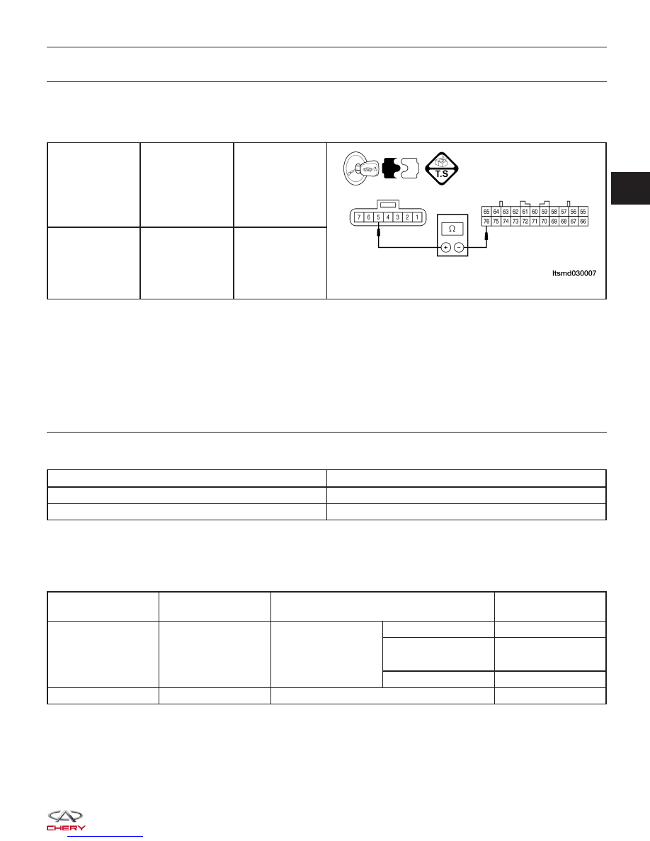
• Check harness continuity between following terminals.

A/T SENSOR

TERMINAL

ECM

TERMINAL

CONTINUITY

5

76

Yes

• Continuity should exist.

• Check harness for short to power and short to ground.

Is the check result normal?

Yes

>>

Go to the next step.

No

>>

Repair circuit for an open or short to power or short to ground in harness or connectors.

5.

CHECK IAT SENSOR

• Check resistance between MAF sensor terminal 5 and 6 under the following conditions:

IAT°C

RESISTANCE K

20°C

2.3 - 3.0

80°C

0.30 - 0.42

• Connect IAT sensor connector.

• Connect ECM connector.

• Turn ignition switch on.

• Check sensor signal output.

TERMINAL NO.

ITEM

CONDITION

DATA (DC

VOLTAGE)

56

IAT sensor

Ignition switch: ON

IAT: 0°C

3.2 - 3.8 V

IAT: 20°C

2.3 - 2.9 V

IAT: 40°C

1.5 - 2.1 V

IAT: 80°C

0.4 - 1.0 V

76

Sensor (GND)

Ignition switch: ON

0 V

Is the check result normal?

Yes

>>

Go to the next step.

No

>>

Replace IAT sensor.

DIAGNOSIS & TESTING

03


6.

CHECK DTC

• With the X-431 scan tool, read ECM DTCs.

• Refer to ⬙DTC Confirmation Procedure⬙.

Is DTC 13 still present?

Yes

>>

Replace the ECM.

No

>>

The system is now operating properly.
Reassemble the vehicle and road test to verify the customers complaint is repaired.

DIAGNOSIS & TESTING


14 - Throttle Position Sensor

DIAGNOSIS & TESTING

LTSMW030014T

03


Check reference values between ECM terminals and ground under the following conditions:

ECM TERMINAL

NO.

ITEM

CONDITION

DATA (DC

VOLTAGE)

65

Regulated sensor

supply

Ignition switch: ON

-

Approximately 5 V

68

Throttle Position

(TP) sensor

TP is in idle position

0.3 - 1.0 V

TP is full opening

4.5 - 5.5 V

71

Idle position switch

Adjust TP to idle

position

0 - 1 V

TP is ajar

Above 4 V

76

Sensor (GND)

-

Approximately 0 V

On Board Diagnostic Logic
• Self-diagnosis detection logic.

DTC NO.

DTC DEFINITION

DTC DETECTION

CONDITION

DTC SET

CONDITION

POSSIBLE CAUSE

14

Throttle position

sensor

Ignition switch on for
60 seconds or after
engine start

• Idle position
switch is in ON
position and output
is over 2 V for 4
seconds
continuously.

• Signal output is
below 0.2 V for 4
seconds
continuously.

• Throttle Position
Sensor (TPS) or
misalignment

• Harness or
connectors

• Idle position switch
ON position is not
normal

• Idle position switch
signal circuit shorted

• ECM

DTC Confirmation Procedure:

Before performing the following procedure, confirm that battery voltage is more than 12 V.

• Turn ignition switch off.

• Connect the X-431 scan tool to the Data Link Connector (DLC) - use the most current software available.

• Turn ignition switch on.

• With the scan tool, record and erase stored DTCs in the ECM.

• Start engine and warm it to normal operating temperature, then select view DTC and data stream.

• If the DTC is detected, the DTC condition is current. Go to Diagnostic Procedure - Step 1.

• If the DTC is not detected, the DTC condition is intermittent (See Diagnostic Help and Intermittent DTC Trou-

bleshooting in Section 03 Electronic Engine Controls for more information.

NOTE :
Before performing the following procedure, make sure that the ECM connection is in good condition.

NOTE :
While performing electrical diagnosis & testing, always refer to the electrical schematics for specific circuit
and component information.

DIAGNOSIS & TESTING


Content   ..  191  192  193  194   ..