Chery Tiggo. Manual - part 158


  Index      Chery     Chery Tiggo - service repair manual 2009 year


Search            


Content   ..  156  157  158  159   ..


Chery Tiggo. Manual - part 158


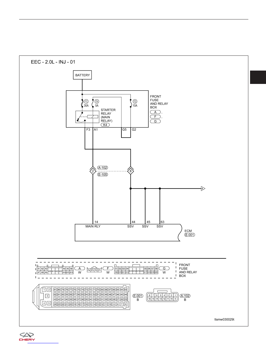
P0201 - Cylinder 1 - Injector Circuit
P0202 - Cylinder 2 - Injector Circuit
P0203 - Cylinder 3 - Injector Circuit
P0204 - Cylinder 4 - Injector Circuit

DIAGNOSIS & TESTING

LTSMW030029T

03


DIAGNOSIS & TESTING

LTSMW030030T


Check reference values between ECM terminals and ground under the following conditions:

ECM TERMINAL NO.

ITEM

CONDITION

DATA (AVERAGE DC

VOLTAGE)

6

Injector 2

• Engine is running

• Warm-up condition

• Idle

• Accelerate suddenly

Voltage: 11 - 14 V

7

Injector 3

27

Injector 1

47

Injector 4

On Board Diagnostic Logic
• Self-diagnosis detection logic.

DTC NO.

DTC DEFINITION

DTC DETECTION

CONDITION

POSSIBLE CAUSE

P0201

Cylinder 1 - Injector Circuit

Engine is running

• Injector

• Harness or connectors

• ECM

P0202

Cylinder 2 - Injector Circuit

P0203

Cylinder 3 - Injector Circuit

P0204

Cylinder 4 - Injector Circuit

DTC Confirmation Procedure:

Before performing the following procedure, confirm that battery voltage is more than 12 V.

• Turn ignition switch off.

• Connect the X-431 scan tool to the Data Link Connector (DLC) - use the most current software available.

• Turn ignition switch on.

• With the scan tool, record and erase stored DTCs in the ECM.

• Start engine and warm it to normal operating temperature then select view DTC.

• If DTC is detected, go to Diagnostic Procedure - Step 1.

• If the DTC is not detected, the DTC condition is intermittent (See Diagnosis & Testing Diagnostic Help in Sec-

tion 03 Electronic Engine Controls).

NOTE :
While performing electrical diagnosis & testing, always refer to the electrical schematics for specific circuit
and component information.

Diagnostic Procedure

1.

CHECK GROUND CONNECTIONS

• Turn ignition switch off.

• Loosen and retighten ground screws on the body (See Ground Inspection in Section 03 Electronic Engine Con-

trols).

• Inspect ground connections E-207 and E-208 mounting position (See Vehicle Wiring Harness Layout - Engine

Room Harness (With 2.0L Engine) in Section 16 Wiring).

Are the ground connections OK?

Yes

>>

Go to the next step.

No

>>

Repair or replace ground harness or connections.

DIAGNOSIS & TESTING

03


2.

INSPECTION START

• Start engine.

Is any cylinder ignited?

Yes

>>

If with the X-431, go to the next step.
If without the X-431, go to step 4.

No

>>

Go to step 5.

3.

PERFORM ACTIVE TEST FUNCTION

• Start engine.

• Select ⬙ACTIVE TEST⬙ menu.

• Perform injector active test.

• Make sure that each test produces a momentary engine speed drop.

Is the check result normal?

Yes

>>

Go to step 11.

No

>>

Go to step 5.

4.

CHECK FUNCTION OF INJECTORS

• Listen to injectors for operating sound one by one.

Does a clicking noise exist for all injectors?

Yes

>>

Go to step 11.

No

>>

Go to the next step.

5.

CHECK INJECTOR ELECTRICAL CONNECTOR

• Turn ignition switch off.

• Disconnect the injector electrical connector (1).

• Inspect the electrical connector for damage.

Is the electrical connector OK?

Yes

>>

Go to the next step.

No

>>

Repair or replace the electrical connector

as necessary.

DIAGNOSIS & TESTING

BESM040006


Content   ..  156  157  158  159   ..