Chery Tiggo. Manual - part 121


  Index      Chery     Chery Tiggo - service repair manual 2009 year


Search            


Content   ..  119  120  121  122   ..


Chery Tiggo. Manual - part 121


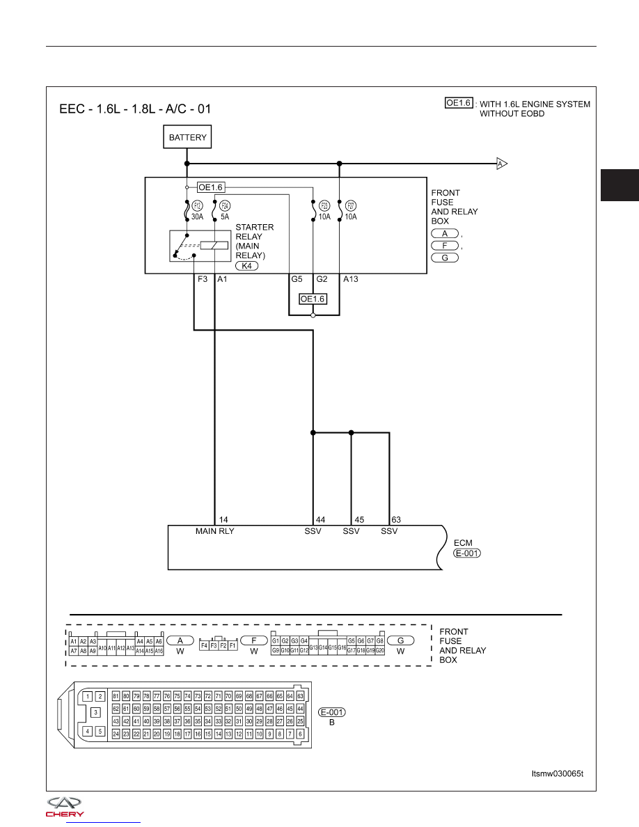
P0645 - A/C Clutch Relay Circuit

DIAGNOSIS & TESTING

LTSMW030065T

03


DIAGNOSIS & TESTING

LTSMW030066T


Check reference values between ECM terminals and ground under the following conditions:

ECM TERMINAL NO.

ITEM

CONDITION

DATA (AVERAGE DC

VOLTAGE)

69

Air compressor relay

• After engine has been
started for 5 seconds, A/C
can be turned on.

• If IAT is above 140.3°C ,
A/C will be shut off.

• If ECT is above
140.3°C, A/C will be shut
off. If ECT is below
111.8°C, A/C will resume.

• If A/C high side
pressure is above 20.0
bar, A/C will be shut off. If
A/C high side pressure is
below 19.5 bar, A/C will
resume.

• If evaporator
temperature is below
1.5°C, A/C will be shut off.
If evaporator temperature
is above 4.5°C, A/C will
resume.

• If system voltage is
below 8.04 V, A/C will be
shut off. If system voltage
is above 10.01 V, A/C will
resume.

0 V or 12 V

On Board Diagnostic Logic
• Self-diagnosis detection logic.

DTC NO.

DTC DEFINITION

DTC DETECTION

CONDITION

DTC SET

CONDITION

POSSIBLE CAUSE

P0645

A/C clutch relay

circuit

Engine is running

ECM detected that
the input signal is
out of the
acceptable range.

• Fuse

• A/C compressor
relay

• Harness or
connectors

• ECM

DTC Confirmation Procedure:

Before performing the following procedure, confirm that battery voltage is more than 12 V.

• Turn ignition switch off.

• Connect the X-431 scan tool to the Data Link Connector (DLC) - use the most current software available.

• Turn ignition switch on.

• With the scan tool, record and erase stored DTCs in the ECM.

• Start engine and warm it up to the normal operating temperature.

• Turn A/C switch on then select view DTC.

• If DTC is detected, go to Diagnostic Procedure - Step 1.

• If the DTC is not detected, the DTC condition is intermittent (See Diagnosis & Testing Diagnostic Help in Sec-

tion 03 Electronic Engine Controls).

NOTE :
While performing electrical diagnosis & testing, always refer to the electrical schematics for specific circuit
and component information.

DIAGNOSIS & TESTING

03


Diagnostic Procedure

1.

CHECK GROUND CONNECTIONS

• Turn ignition switch off.

• Loosen and retighten ground screws on the body (See Ground Inspection in Section 03 Electronic Engine Con-

trols).

• Inspect ground connections E-207 and E-208 mounting position (See Vehicle Wiring Harness Layout - Engine

Room Harness (With 1.6L/1.8L Engine) in Section 16 Wiring).

Are the ground connections OK?

Yes

>>

Go to the next step.

No

>>

Repair or replace ground connections.

2.

CHECK A/C CLUTCH RELAY CONTROL CIRCUIT

• Turn off A/C switch.

• Check A/C clutch relay control circuit supply voltage

between ECM terminal 69 and ground in the ECM
electrical connector E-001.

• Battery voltage should exist.

Is the check result normal?

Yes

>>

Go to step 4.

No

>>

Go to the next step.

3.

DETECT MALFUNCTIONING PART

• Check the following:

− Fuse FB18, SB2
− Front fuse and relay box K, E, J
− A/C compressor relay, EMS relay (R2)
− Check harness for an open or short between ECM terminal 69 and fuse 12.

Is the check result normal?

Yes

>>

Go to the next step.

No

>>

Repair or replace malfunctioning part.

DIAGNOSIS & TESTING

LTSMD030065


Content   ..  119  120  121  122   ..