Chery Tiggo. Manual - part 110


  Index      Chery     Chery Tiggo - service repair manual 2009 year


Search            


Content   ..  108  109  110  111   ..


Chery Tiggo. Manual - part 110


3.

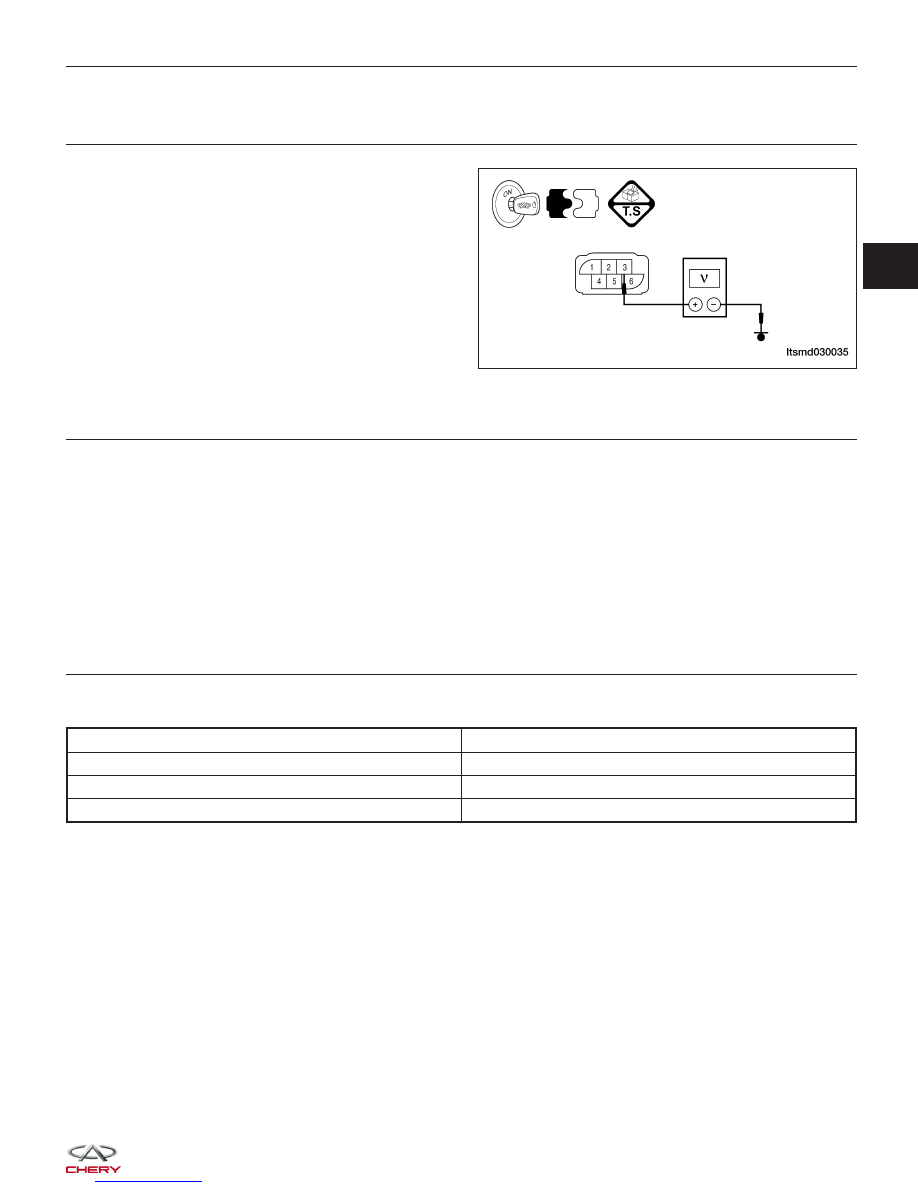
CHECK THE THROTTLE POSITION SENSOR (TPS) POWER SUPPLY CIRCUIT

• Turn ignition switch on.

• Check TPS supply voltage between TPS terminal 3

and ground in the TPS electrical connector E-027.

• Approximately 5 V should exist.

Is the check result normal?

Yes

>>

Go to step 8.

No

>>

Go to the next step.

4.

CHECK THE TPS POWER SUPPLY CIRCUIT

• Turn ignition switch off.

• Disconnect ECM harness connector.

• Check harness continuity between TPS terminal 3 and ECM terminal 32.

• Continuity should exist.

Is the check result normal?

Yes

>>

Go to the next step.

No

>>

Repair or replace circuit for an open.
If the circuit is normal, go to the next step.

5.

CHECK THE TPS AND THE ACCELERATOR PEDAL POSITION (APP) SENSOR POWER SUPPLY CIRCUIT

• Check harness for short to power and short to ground between following terminals.

ECM TERMINAL

TPS/APS TERMINAL

32

TPS terminal 3

32

APP sensor terminal 3

33

APP sensor terminal 6

Is the check result normal?

Yes

>>

Go to the next step.

No

>>

Repair circuit for short to ground or short to power in harness or connectors.

DIAGNOSIS & TESTING

LTSMD030035

03


6.

CHECK THE APP SENSOR

• Connect all harness connectors disconnected.

• Turn ignition switch on.

• Check voltage between ECM terminals 16 (APP sensor 1 signal), 40 (APP sensor 2 signal) and ground under

the following conditions:

ECM

TERMINAL

NO.

APP

SENSOR

TERMINAL

ITEM

CONDITION

VOLT (DC

VOLTAGE)

16

APP

sensor

terminal 4

Accelerator

Pedal

Position

Sensor 1

(APPS1)

Turn

ignition

switch on

• Engine
stopped

Accelerator
pedal:
Fully
released

0.72 -

0.74 V

• Engine
stopped

Accelerator
pedal:
Fully
depressed

3.95 V

40

APP

sensor

terminal 1

Accelerator

Pedal

Position

Sensor 2

(APPS2)

• Engine
stopped

Accelerator
pedal:
Fully
released

0.36 -

0.37 V

• Engine
stopped

Accelerator
pedal:
Fully
depressed

1.97 V

Is the check result normal?

Yes

>>

Go to step 10.

No

>>

Replace the Accelerator Pedal Assembly (See Accelerator Pedal Position Sensor Removal & Installation

in Section 03 Electronic Engine Controls).

7.

CHECK THE TPS SIGNAL CIRCUIT FOR AN OPEN AND SHORT

• Turn ignition switch off.

• Disconnect ECM harness connector.

• Check harness continuity between electronic throttle control actuator terminal 5 and ECM terminal 38.

• Continuity should exist.

• Also check harness for a short to power and short to ground.

Is the check result normal?

Yes

>>

Go to the next step.

No

>>

Repair circuit for an open or short to power or short to ground in harness or connectors.

DIAGNOSIS & TESTING


8.

CHECK THE TPS SENSOR GROUND CIRCUIT FOR AN OPEN AND SHORT

• Check harness continuity between electronic throttle control actuator terminal 2 and ECM terminal 78.

• Continuity should exist.

• Check harness for short to power and short to ground.

Is the check result normal?

Yes

>>

Go to the next step.

No

>>

Repair or replace circuit for an open or short to power or short to ground in harness or connectors.

9.

CHECK TPS

• Connect all harness connectors disconnected.

• Turn ignition switch on.

• Check voltage between TPS terminals 6 (TPS1) and ground, terminal 5 (TPS2) and ground under the following

conditions:

TPS

TERMINAL

NO.

ITEM

CONDITION

VOLTAGE

(DC

VOLTAGE)

5

Throttle

Position

Sensor 2

(TPS2)

Ignition
switch: ON

• Engine

stopped

Accelerator
pedal:
Fully
released

4.24 V

• Engine

stopped

Accelerator
pedal:
Fully
depressed

0.72 V

6

Throttle

Position

Sensor 1

(TPS1)

• Engine

stopped

Accelerator
pedal:
Fully
released

0.74 V

• Engine

stopped

Accelerator
pedal:
Fully
depressed

4.62 V

Is the check result normal?

Yes

>>

Go to the next step.

No

>>

Replace electronic throttle control actuator, and perform throttle valve position learning.

DIAGNOSIS & TESTING

03


10.

CHECK DTC

• With the X-431 scan tool, read ECM DTCs.

• Refer to ⬙DTC Confirmation Procedure⬙.

Is DTC P0221 still present?

Yes

>>

Replace the ECM.

NOTE : The Immobilizer control module must be matched to the new ECM (See ECM Removal & Instal-

lation in Section 03 Electronic Engine Controls).

No

>>

The system is now operating properly.
Reassemble the vehicle and road test to verify the customers complaint is repaired.

DIAGNOSIS & TESTING


Content   ..  108  109  110  111   ..