Chery Tiggo. Manual - part 109


  Index      Chery     Chery Tiggo - service repair manual 2009 year


Search            


Content   ..  107  108  109  110   ..


Chery Tiggo. Manual - part 109


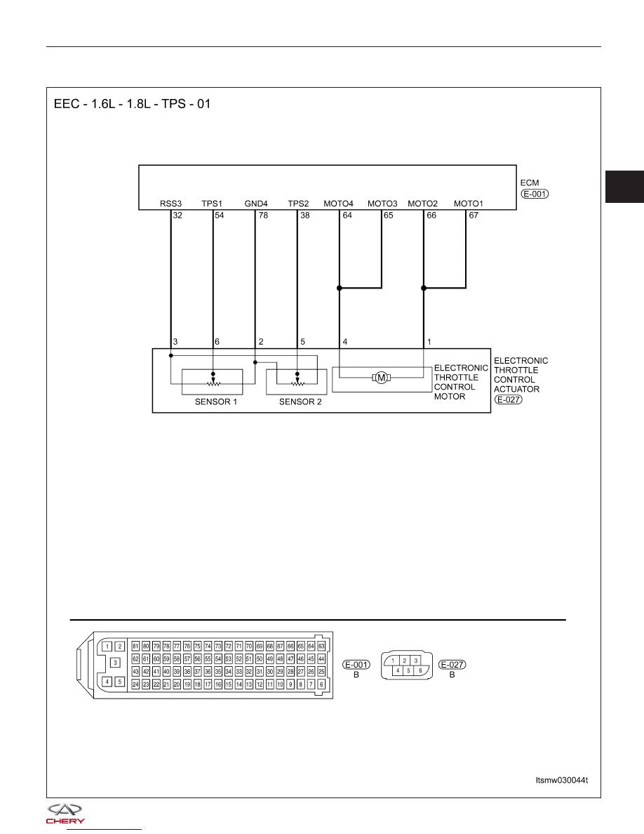
P0221 - Throttle Position Sensor B Performance

DIAGNOSIS & TESTING

LTSMW030044T

03


DIAGNOSIS & TESTING

LTSMW030045T


Check reference values between ECM terminals and ground under the following conditions:

ECM TERMINAL

NO.

ITEM

CONDITION

DATA (DC

VOLTAGE)

32

Regulated sensor

supply 2

Ignition switch: ON

-

Approximately 5 V

38

Electronic throttle

control actuator

(Position sensor)

• Engine stopped

• Accelerator pedal:
Fully released

4.24 V

• Engine stopped

• Accelerator pedal:
Fully depressed

0.72 V

54

Electronic throttle

control actuator

• Engine stopped

• Accelerator pedal:
Fully released

0.74 V

• Engine stopped

• Accelerator pedal:
Fully depressed

4.62 V

78

Sensor (GND)

-

Approximately 0 V

64

Motor 4

0 V or 12 V

65

Motor 3

66

Motor 2

12 V or 0 V

67

Motor 1

On Board Diagnostic Logic
• Self-diagnosis detection logic.

DTC NO.

DTC DEFINITION

DTC DETECTION

CONDITION

DTC SET
CONDITION

POSSIBLE CAUSE

P0221

Throttle Position

Sensor (TPS) B

performance

Ignition switch on or

after engine start

Rationally incorrect
voltage is sent to
ECM compared with
the signals from
TPS1 and TPS2.

• Electronic throttle
control actuator
(TPS1 and TPS2)

• Harness or
connectors (The
sensor signal circuit
is open or shorted)

• Accelerator pedal
position sensor 2

• ECM

DTC Confirmation Procedure:

Before performing the following procedure, confirm that battery voltage is more than 12 V.

• Turn ignition switch off.

• Connect the X-431 scan tool to the Data Link Connector (DLC) - use the most current software available.

• Turn ignition switch on.

• With the scan tool, record and erase stored DTCs in the ECM.

• Start engine and warm it to normal operating temperature then select view DTC.

• If DTC is detected, go to Diagnostic Procedure - Step 1.

• If the DTC is not detected, the DTC condition is intermittent (See Diagnosis & Testing Diagnostic Help in Sec-

tion 03 Electronic Engine Controls).

NOTE :
While performing electrical diagnosis & testing, always refer to the electrical schematics for specific circuit
and component information.

DIAGNOSIS & TESTING

03


Diagnostic Procedure

1.

CHECK GROUND CONNECTIONS

• Turn ignition switch off.

• Loosen and retighten ground screws on the body (See Ground Inspection in Section 03 Electronic Engine Con-

trols).

• Inspect ground connections E-207 and E-208 mounting position (See Vehicle Wiring Harness Layout - Engine

Room Harness (With 1.6L/1.8L Engine) in Section 16 Wiring).

Are the ground connections OK?

Yes

>>

Go to the next step.

No

>>

Repair or replace ground connections.

2.

CHECK THROTTLE POSITION SENSOR (TPS) ELECTRICAL CONNECTOR

• Disconnect the TPS (1) electrical connector.

• Inspect the electrical connector for damage.

Is the electrical connector OK?

Yes

>>

Go to the next step.

No

>>

Repair or replace the electrical connector

as necessary.

DIAGNOSIS & TESTING

VISMD030203


Content   ..  107  108  109  110   ..