Chery Tiggo. Manual - part 35


  Index      Chery     Chery Tiggo - service repair manual 2009 year


Search            


Content   ..  33  34  35  36   ..


Chery Tiggo. Manual - part 35


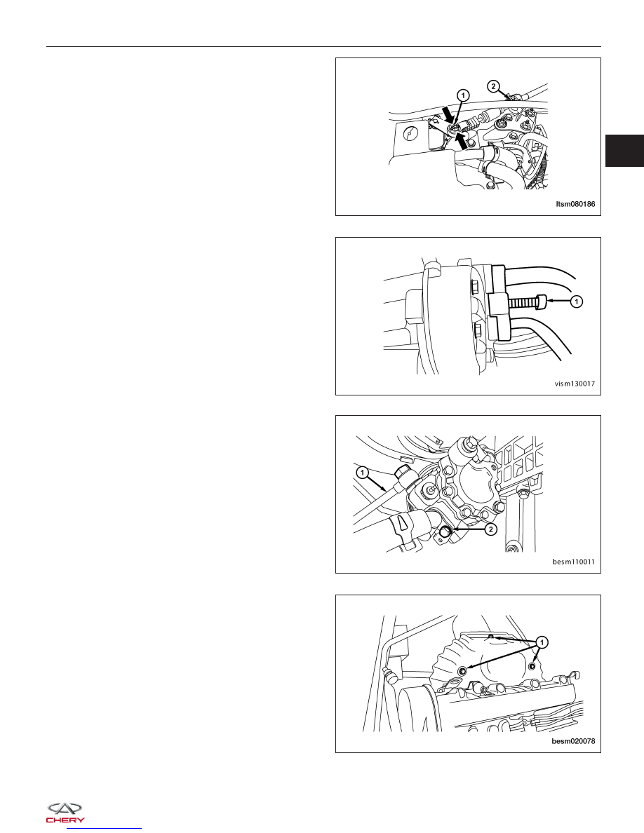
20. If equipped with an automatic transaxle remove the

transaxle shift cable (1) and the shift cable clamp
(2).

21. Remove the A/C compressor line bolt (1) from the

A/C compressor.
(Tighten: A/C compressor line bolts to 20 N·m)

NOTE :
After removing the A/C lines, plug the A/C lines to pre-
vent any debris from entering the A/C system.

22. Remove the high pressure line (1) and low pres-

sure line (2) from the power steering pump (drain
fluid from lines).
(Tighten: High pressure line to power steering
pump 40 ± 5 N·m)
(Tighten: Low pressure line to power steering pump
40 ± 5 N·m)

23. Remove the exhaust manifold heat shield bolts (1)

and then remove heat shield.
(Tighten: Exhaust manifold heat shield bolts to 15
N·m)

24. Disconnect the upstream and downstream oxygen sensor connectors.

ON-VEHICLE SERVICE

LTSM080186

VISM130017

BESM110011

BESM020078

02


25. Remove the catalytic converter to exhaust manifold

bolts (1).

26. Raise and support the vehicle.

27. Remove the front axle shaft (See Front Axle Shaft Removal & Installation in Section 09 Driveline & Axle).

28. Drain the engine oil.

29. Lower the vehicle and install engine lift chain hangers.

30. Remove the bolts (1) securing the front engine

mount.
(Tighten: Engine front mount bolt to 60 N·m)

31. Remove the bolts (1) securing the rear engine

mount.
(Tighten: Engine rear mount bolt to 60 N·m)

ON-VEHICLE SERVICE

LTSM020201

BESM080035

LTSM020207


32. Remove the left transaxle mount bolts (2) and the

transaxle mount bracket retaining bolts (1).
(Tighten: Left transaxle mount bolt to 70 N·m)

33. Using special tool CH-20001 (2), remove the three

bolts (1) securing the right engine mount.
(Tighten: Engine right mount bolt to 70 N·m)

34. Verify all components between the engine and vehicle are disconnected.

35. Remove the front sub-frame (See Front Sub-Frame Removal & Installation in Section 10 Suspension).

36. Hoist the engine from vehicle.

CAUTION:
Verify all electrical connectors are disconnected prior to engine/transaxle removal.

37. Separate engine and transaxle.

ON-VEHICLE SERVICE

LTSM020156

LTSM020218

02


38. Remove the accessory drive belt (1) (See Acces-

sory Drive Belt Removal & Installation in Section
02 Engine).

39. Remove the generator (1) from the bracket (See

Generator Removal & Installation in Section 05
Starting & Charging).

40. Remove the A/C compressor pipe.

41. Remove the A/C compressor (2) (See A/C Com-

pressor Removal & Installation in Section 13 Heat-
ing & Air Conditioning).

42. Remove the power steering pump (1) with piping

connected and set aside with wire.

43. Installation is in the reverse order of removal.

ON-VEHICLE SERVICE

LTSM020200

BESM020029

BESM020028


Content   ..  33  34  35  36   ..