Chery Tiggo. Manual - part 29
Engine Hoist
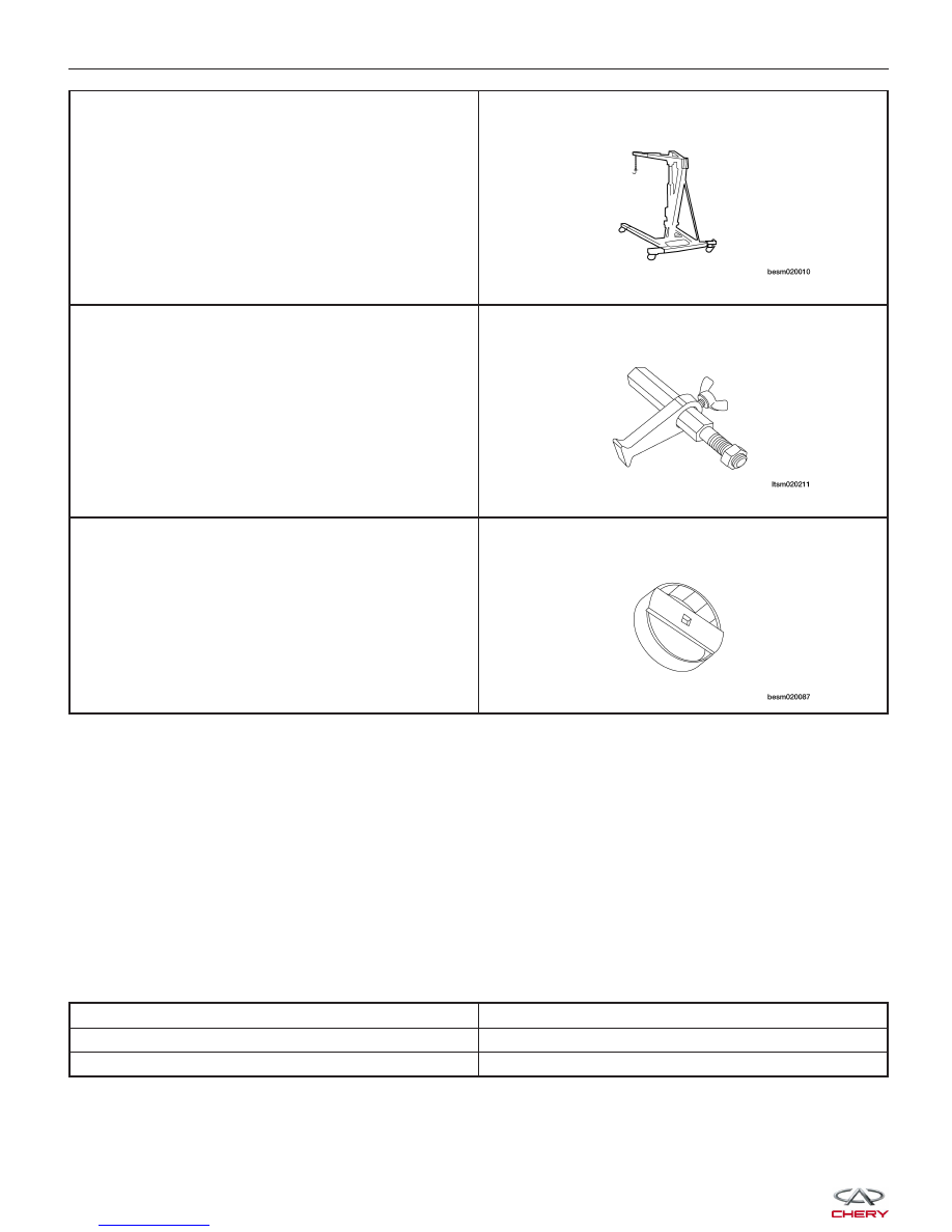
Flywheel Fixture
CH-20043
Oil Filter Remover
CH-10003
Lubrication System
The engine lubrication system operates as follows:
• Oil is drawn into the oil pump through the oil pump strainer tube in the sump of the oil pan.
• Oil is pumped through the oil filter on the cylinder block.
• Oil enters the main oil gallery where it is distributed to the crankshaft main journals and to the cylinder head.
• From the main journals, the oil is routed through cross-drilled passages in the crankshaft to lubricate the con-
necting rod bearings. Controlled leakage through the crankshaft main bearings and connecting rod bearings is
slung radially outward to cool and lubricate the cylinder walls as well as the entire connecting rod, piston and
piston ring assembly.
• The engine lubrication system is a full-flow filtration, pressure feed type. The oil pump body is mounted to the
engine block. The pump inner rotor is driven by the crankshaft.
Engine Oil Pressure Specifications
Lower Idle Speed (800 ± 50 RPM)
1.2 - 1.5 bar
High Idle Speed (2000 RPM)
3.2 - 3.5 bar
High Speed (4000 RPM)
3.7 ± 0.5 bar
GENERAL INFORMATION