Chery Tiggo. Manual - part 26


  Index      Chery     Chery Tiggo - service repair manual 2009 year


Search            


Content   ..  24  25  26  27   ..


Chery Tiggo. Manual - part 26


ITEM

SPECIFICATION (mm)

Valve Outer Diameter

Intake Valve

5.98 ± 0.008

Exhaust Valve

5.96 ± 0.008

Valve Guide Inner Diameter

Intake Valve

5.4 ± 0.1

Exhaust Valve

5.4 ± 0.1

Fringe Thickness On Top Of Valve

Intake Valve

0.3 ± 0.15

Exhaust Valve

0.3 ± 0.15

Valve Tilt Angle

Intake Valve

65°

Exhaust Valve

68°

Valve Height

Intake Valve

107.998

Exhaust Valve

106.318

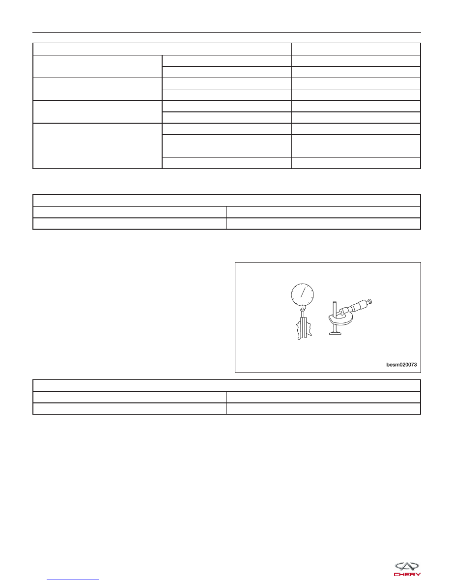
• Measure valve deflection.

VALVE DEFLECTION LIMIT (DIAL GAUGE READING)

Intake

0.02 mm

Exhaust

0.04 mm

• If it exceeds the limit, check valve to valve guide clearance.

− Measure valve stem diameter and valve guide inner diameter.
− Check that clearance is within specification.
− If it exceeds the limit, replace valve or valve

guide.

VALVE TO VALVE GUIDE CLEARANCE STANDARD

Intake

0.012 - 0.043 mm

Exhaust

0.032 - 0.063 mm

Assembly

1. Install the valves into the cylinder head (larger diameter on intake side).

2. Install the valve springs.

3. Install the valve spring retainers.

CYLINDER HEAD UNIT REPAIR

BESM020073


4. Using valve spring compressor CH-20018 (1), com-

press the valve springs.

5. Install the valve keepers.

6. Strike the valve stem lightly with a plastic hammer after installation to verify proper assembly.

Valve Springs

Specifications

Valve Spring Specifications

DESCRIPTION

SPECIFICATION (mm)

Spring Free Length

47.7

Spring Height At 620 Newtons Of Pressure

32.0

Disassembly

NOTE :
The following special tools are required to perform the repair procedure:
• CH-20011 - Valve Seal Installer

• CH-20012 - Valve Stem Seal Installer Guide

• CH-20013 - Valve Seal Remover

• CH-20017 - Valve Keeper Installer

• CH-20018 - Valve Spring Compressor

1. Using the special tool CH-20018 (1), compress the

valve springs.

CYLINDER HEAD UNIT REPAIR

BESM020067

BESM020067

02


2. Remove the valve keeper (1), valve spring retainer

(2).

3. Remove the valve springs (3) from the cylinder

head.

Inspection

• Whenever valves have been removed for inspection, reconditioning or replacement, valve springs should be

tested for correct load.

• Discard the springs that do not meet specifications.

• The following specifications apply to both intake

and exhaust valve springs.

VALVE SPRING LENGTH/HEIGHT

Spring Free Length

47.7 mm

Spring Height At 620 Newtons Of Pressure

32.0 mm

If it is not within specifications, replace the valve spring.

CYLINDER HEAD UNIT REPAIR

VISM080040

BESM020072


Assembly

1. Install the valve springs.

2. Install the valve spring retainers.

3. Using valve spring compressor CH-20018 (1), com-

press the valve springs.

4. Install the valve keepers.

5. Strike the valve stem lightly with a plastic hammer after installation to verify proper assembly.

CYLINDER HEAD UNIT REPAIR

BESM020067

02


Content   ..  24  25  26  27   ..