Chery Tiggo. Manual - part 24


  Index      Chery     Chery Tiggo - service repair manual 2009 year


Search            


Content   ..  22  23  24  25   ..


Chery Tiggo. Manual - part 24


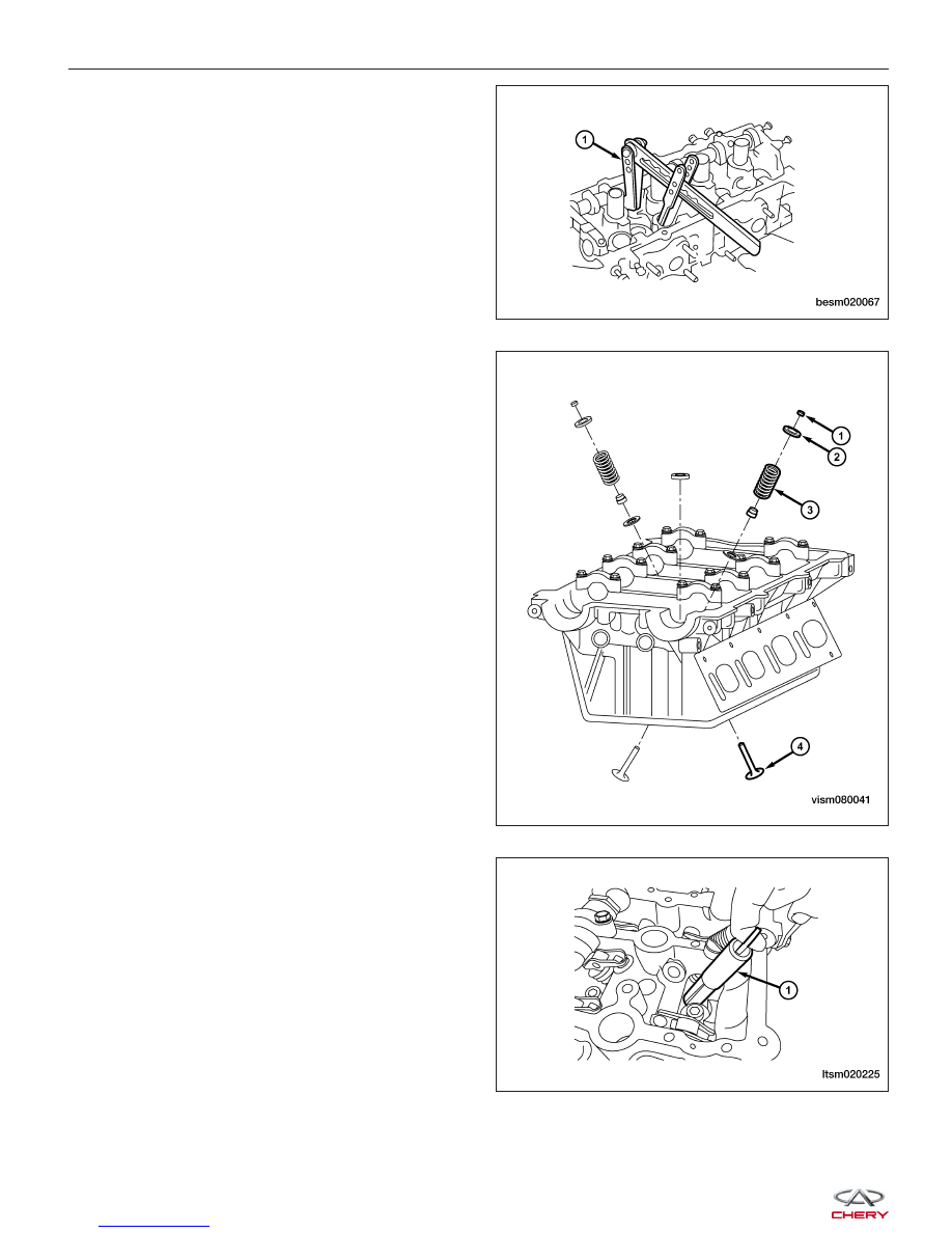
3. Using the special tool CH-20018 (1), compress the

valve spring.

4. Remove the valve keeper (1), valve spring retainer

(2) and valve spring (3).

5. Push the valve stem from the cylinder head and

remove the valve (4).

6. Using special tool CH-20013 (1), remove the valve

oil seal.

7. Remove the valve guide.

8. Remove the spark plugs.

CYLINDER HEAD UNIT REPAIR

BESM020067

VISM080041

LTSM020225


Inspection

• Cylinder head must be flat within 0.04 mm.

• Inspect camshaft bearing journals for scoring.

• Remove carbon and varnish deposits from inside of

valve guides with a valve guide cleaner.

• Verify the valve tappets move freely in their bores,

and that they have been rotating.

• Check the valve guide height.

Assembly

1. Install new valve guide if necessary.

2. Install new valve seat if necessary.

3. Using special tool CH-20011 (1) and CH-20012 (2),

install the new valve oil seal.

4. Install the valves into the cylinder head (larger diameter on intake side).

5. Install the valve springs.

6. Install the valve spring retainers.

CYLINDER HEAD UNIT REPAIR

BESM020068

LTSM020224

02


7. Using valve spring compressor CH-20018 (1), com-

press the valve springs.

8. Install the valve keepers.

9. Strike the valve stem lightly with a plastic hammer after installation to verify proper assembly.

10. Install valve tappets in the head.

11. Install the camshafts.

Installation Notes:
• Coat the valve oil seal with engine oil.

Camshaft

Specifications

Camshaft Specifications

DESCRIPTION

SPECIFICATION (mm)

Intake Cam Lobe Height

37.15

Exhaust Cam Lobe Height

37.05

Journal #1 Outer Diameter

31.934 - 31.95

Journal #2, #3, #4, #5, Outer Diameter

23.947 - 23.96

Cam Bearing #1 Inner Diameter

32 - 32.025

Cam Bearing #2, #3, #4, #5, Inner Diameter

24 - 24.021

Journal #1 Clearance

0.05 - 0.091

Journal #2, #3, #4, #5 Clearance

0.04 - 0.074

Intake Camshaft Axial Clearance

0.15 - 0.20

Exhaust Camshaft Axial Clearance

0.15 - 0.20

CYLINDER HEAD UNIT REPAIR

BESM020067


Disassembly

1. Remove the camshaft bearing cap bolts.

NOTE: Equally loosen camshaft bearing cap bolts
in several steps.

2. Remove the camshaft bearing caps and place them in proper order.

NOTE: The camshaft bearing caps are marked for identification.

3. Remove the camshafts and then remove the camshaft seals.

Inspection

• Measure the camshaft cam lobe height.

• If wear is beyond the limit, replace the camshaft.

CAMSHAFT CAM LOBE HEIGHT

Intake Cam Lobe Height

37.15 mm

Exhaust Cam Lobe Height

37.05 mm

CYLINDER HEAD UNIT REPAIR

BESM020035

BESM020037

02


Content   ..  22  23  24  25   ..