Chery SQR 7160 sedan. Manual - part 120


  Index      Chery     Chery SQR 7160 sedan - service repair manual


Search            


Content   ..  118  119  120  121   ..


Chery SQR 7160 sedan. Manual - part 120


10 

3820.2 3537.5 4102.9 

20 

2509.3 2346.2 2672.4 

2051.3 1928.2 2174.4 

30 

1686.0 1584.9 1787.1 

40 1157.1 

1088.8 

1225.4 

50 

810.0 763.0 857.0 

60 

577.6 548.7 606.5 

70 

419.1 395.6 442.6 

80 

309.0 292.0 326.0 

90 

231.4 218.7 244.1 

100 

175.7 166.2 185.2 

110 

135.2 127.0 143.3 

120 105.4 

98.6 

112.2 

130  83.1 77.3 88.9 

●Testing method: 

a  Ohmmeter method 

Using ohmmeter measure resistance. Determine if ECU sensor operates by abve engine air 

intake temperate-resistance chart. Remove air intake temperature sensor, and heat sensor in 

water (refer to diagram 4.3). Sensor has a corresponding resistance with different 

temperature. 

b  Voltmeter method 

Install sensor on engine, start engine. Connect voltmeter to sensor signal lead. For different 

air intake temperate, voltmeter has a corresponding voltage drop. Voltage decrease as   

temperature increase. 


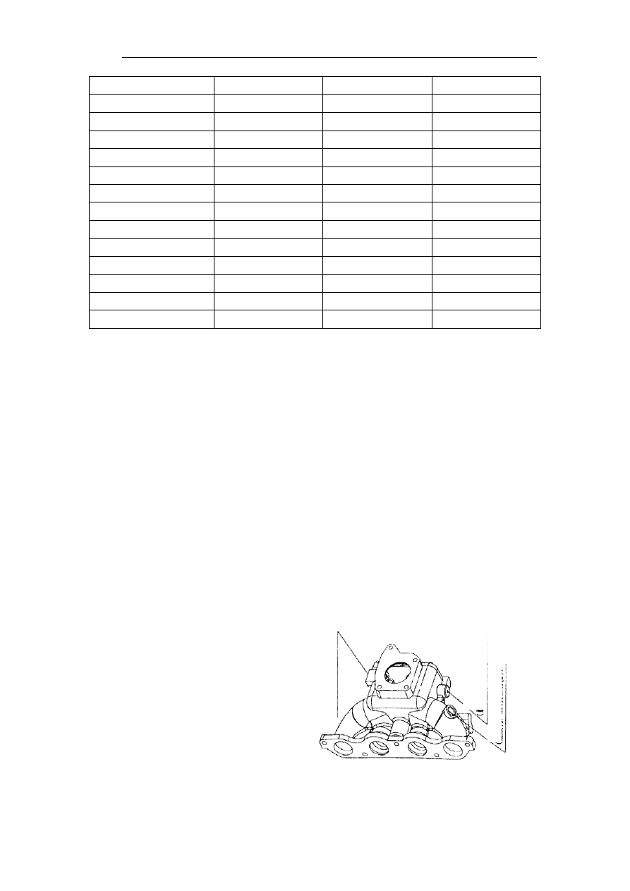
2.3.3 air intake manifold 

2.3.3.1    air intake manifold upper body 


(bo

lt th

re

a

d

 hole

)

co

nn

ect

or

-f

u

el pr

ess

u

re

lt

(bolt thre

ad


hol

e)

 M1

4

(bo

lt th

re

a

d

hol

e) M1

2

i


2.3.3.2    air intake manifold lower body 


2.4 fuel vapor control system 

In order that air could be exchanged for fuel tank, and to prevent fuel vapor from exhausting 

to atmosphere,  fuel vapor is absorbed by active carbon and stored in it. Upon engine 

operating condition, stored fuel vapor will be timely and adequately sent to air intake hose 

and burned with mixture in combustion chamber.       

SQR480EC multi-port fuel injection system using and servicing 

3.1 fuel and purge system using and servicing 

3.1.1 Fuel grade used in Chery engine must be higher than 93#RON, and leaded gasoline or 

fuel grade lower than 93#RON CAN NOT be used.  Leaded oil could do harm to the 

3-way catalyst, resulting in the loss of oxidization and reduction function to harmful 

materials in exhaust. Lower grade gas will cause fuel injector being blocked, pin valve and 

regulator etc. being damaged, shortening components lifetime. Using leaded gasoline will 

cause a damaged 3-way catalyst converter, after which 3-way catalyst converter function 

will not recover even the right gas is used.    If leaded fuel is added, the vehicle should be 

driven to specified repairing workshop and repaired as soon as possible. 
★  3-way catalyst converter lose its function under following conditions, which should be 

avoided. 

Burned under high temperature. The ideal temperature for a high purge ratio and long life 

time is s 400-800℃. A higher temperature will cause overheat catalyst, fast ageing, losing 

catalyst function; 

Catalyst hole blocked; 

(3)   Under an over 800℃  temperature and last for 30 seconds, remaining gas in catalyst 

will cause 3-way catalyst converter being damaged. Therefore when engine operating, 

removing ignition coil wire for an operational engine is absolutely forbidden.   

3.1.3 Poor engine operation may cause 3 way catalyst converter being damaged. Therefore, 

scheduled technique service must be done as per Servicing Manual. 

3.1.4 Before engine stalls, let engine idle for some time and cool down gradually, lower heat 

impact strength which will do good to a prolonged engine components and 3 way catalyst 

converter life time.   

3.1.5 After a long-time driving, the vehicle CAN NOT be immediately parked in a place 

where the 3-way catalyst may reaches flammable materials to avoid accidents caused by 

high temperature 3 way catalyst converter. 

3.1.6 DO NOT depress throttle pedal when starting. ECU determines engine operating 

conditions upon throttle position. Once throttle pedal is depressed, throttle is opened and 

ECU cannot determine if engine is under operating condition and can not supply fuel 

correctoly. 

Water temperature sensor

Beside is

elbow of water


3.1.7 After cool starting, the engine is in fast idle. With water temperature increasing, 

engine speed decrease. After engine warming up (water temperature above 85  ℃), engine 

speed stabilize at 950±50r/min. 


3.1.8 Wrap pipe connector with plastic cloth when servicing fuel pipe, preventing fuel 

splash. DO NOT smoke or fire to avoid fire hazard.   


3.1.9 DO NOT remove injector to check fuel injecting condition. DO NOT spray to sky to 

avoid explosion and combustion from spark. 


3.1.10 Check whole fuel pipe circuit leakage frequently and fuel leakage problem should be 

immediately repaired.. 


3.1.11 Set screw for controlling throttle idle position on throttle valve has been precisely 

adjusted and any adjustment is forbidden. 

3.2 Electrical system using and servicing 


3.2.1 Stop vehicle and turn ignition off after stopping. 


3.2.2 Lead on battery MUST BE removed before removing electrical connector.   


3.2.3 Voltage supplied to engine is battery voltage and to avoid ECU damaging for over 

voltage, any other external voltage supply such as fast-charging, starter voltage stabilizing 

power CAN NOT be used to start engine. 


3.2.4 ECU, sensor and actuator elements must be protected from humidity, static electricity, 

and strong electronic interference  (wiring harness must be at least 50 cm away from 

high-tense wire),. Avoid equipments falling and dropping when servicing.. 


3.2.5 Do not start engine when loose connection or battery leads exist. 


3.2.6 Disconnecting battery from vehicle circuit is absolutely forbidden when engine is 

under normal operating condition; otherwise a permanent ECU damage will be caused. 


3.2.7 Disconnecting battery from all vehicle circuits when fast-charging battery. 


3.2.8 DO NOT remove and connect harness connectors on ECU when ignition key is at ON 

position avoiding ECU being damaged by over voltage. 


3.2.9 SQR480EC engine utilize high impedance spark and wire, which are special parts for 

such engine, and can not be replaced with common high-tension wire, otherwise ECU will 

be damaged and affect system normal operating. 


III. SQR480EC EI system faults and trouble shooting 


4.1 CAN NOT START ENGINE 


Power check 

1 battery 

2 fuse 

Check ignition system 

problem 


1 ECU voltage 

check 

2 Check ignition 

switch 

3 check starter relay 

4 check starter   

5check connecting 

harness 

Repair or replace defective 

components 


Check ignition 

system falut 

 Check 


1 ignition wire   

2 ignition coil 

3 spark 


check fuel pipe 

pressure and fuel 

injector 


★  ECU power wire diagnostic 


Measure ECU voltage with a digital voltmeter, Pin A16 is positive and pin B16 is negative. 

When ignition is turned on, this pin voltage is 12V. If the voltage is not 12V, check ECU 

fuse and related circuit. 

 
★  Power and ground fault diagnostic 

Computer ground lead is generally connected to battery negative lead. 

1 fuel pressure 

regulator 

2 fuel pump 

3 fuel filter 

4 fuel injector 

5 fuel pipe 

leakage 


Content   ..  118  119  120  121   ..