Chery SQR 7160 sedan. Manual - part 118


  Index      Chery     Chery SQR 7160 sedan - service repair manual


Search            


Content   ..  116  117  118  119   ..


Chery SQR 7160 sedan. Manual - part 118


●Measuring Method 

a ohmmeter method 

Measure resistance with an ohmmeter, and determine if water temperature sensor operates 

upon measured engine coolant temperature and below diagram. Remove coolant 

temperature sensor, immerse into water and heat water. The sensor has different resistance 

at corresponding temperature. 

Water Temperature Sensor Resistance Specification 

Temperature(℃)

Resistance(Ω)

Temp.(℃)

Resistance(Ω) Temp.(℃)

Resistance(

-40 100865 

25 

2795 

90 

241.8

-35 72437 

30 

2240 

95 

207.1

-30 52594 

35 

1806 

100 

178.0

-25 38583 

40 

1465 

105 

153.6

-20 28582 

45 

1195 

110 

133.1

-15 21317 

50 

980 

115 

115.7

-10 16120 

55 

809 

120 

100.9

-5 12261 

60 

671 

125 

88.3

0 9399 

65 

559 

130 

77.5

5 7263 

70 

469 

135 

68.3

10 5658 

75 

395 

140 

60.3

15 4441 

80 

334 

145 

53.4

20 3511 

85 

283 

150 

47.5

b  voltmeter method 

  Install the sensor on the motor, and crank engine. Connect sensor signal lead to 

voltmeter, there are different    voltage drop at different temperature. 
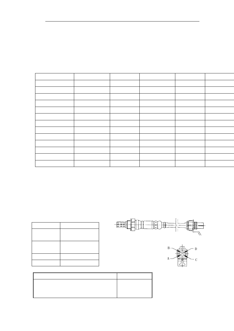
 

Oxygen sensor 

Oxygen sensor is installed on exhaust pipe and accurately regulate excess air co-efficiency . 

Oxygen sensor has 4 leads: C. voltage lead (pin A16) B. signal lead (pin B1)   

A. signal ground (pin B23)      D heater ground (pin B16) 


PIN Function 

C Sensor 

voltage lead 

B Sensor 

signal 

output 

A Signal 

ground 

D Heater 

ground 

Oxygen sensor heater resistance impedance specification table                      

when temperature is 23℃, impedance is 

13.2+/-10%


Resistance Heat Co-efficiency of 

impedance 

(23-800℃) (ppm/℃) 

1150 


When temperature is 800℃, impedance 

is 

25.0+/-10%

When temperature is -40℃, heater 

impedance is 

12.2+/-10%


●Detecting Method: 

a、voltage signal method 

Before testing oxygen sensor, engine must be under normal operation temperature. 
【Note】Only digital voltmeter can be used to test oxygen sensor, otherwise oxygen sensor 

will be damaged. 

 
  During testing, the insulation may be pricked. Before testing, digital voltmeter leads 

must be connected to oxygen sensor ground lead and signal lead. When engine idles and 

under normal temperature, if air/fuel ratio has some difference with ideal air/fuel ratio, the 

oxygen sensor output voltage will vary from low to high periodically. The voltage 

periodically varies from    0.3V to 0.8V. After testing, apply silicon seal gum on pricked 

area. 


A continuously high voltmeter reading indicates an rich air/fuel ratio polluted oxygen 

sensor ambient temperature silicon seal gum or antifreeze agent polluted oxygen sensor or 

leaded fuel used in engine. 


A continuously low voltmeter reading indicates an poor air/fuel ratio, sensor fault. A 

medium reading maintained indicates a possible oxygen sensor fault. 

 
  Remove oxygen sensor from engine. Connect a digital voltmeter lead to sensor, and 

combust sensor sensitive element on propane welding torch flame. The propane flame could 

isolate the sensitive element from oxygen, which will generate voltage. When sensitive 

element is on flame, the voltage is approximately 1V, and when moved away the flame, the 

voltage will drop to 0V. If sensor voltage does not change as specified, replace the oxygen 

sensor.  

 
◆Heating wire diagnostic 

If the heater on sensor does not work, sensor pre-heating will be delayed, and computer 

work time will also be prolonged. Then computer send a wrong rich air/fuel ratio signal, 

wasting the fuel. 


b、Ohmmeter method 

Remove oxygen sensor and connect the ohmmeter between the heating wire and ground 

wire. Referring to above diagram, if the resistance measured is not as specified, replace it 


2.1.5 Speed sensor 
◆  If speed sensor is damaged, the engine can not be started. 


Speed sensor has 2 leads, one is signal lead (pin B7) and the other is ground wire (pin B6)   


⑴ speed sensor 
⑵  belt pulley with teetht 
⑶ signal output 

⑷  signal corresponding to 2   

      mis-teeth. 

Speed sensor determines firing and fuel injection time by monitoring the teeth on the flying 

wheel, engine speed and crankshaft position signal. 

 
● Testing method 

a  ohmmeter method: the coil resistance is 515Ω, 

b oscilloscope 

method: 

Use oscilloscope to monitor pulse waveform, and a voltage pulse will generate when a 

tooth pass by. The flying wheel on this engine have 60-2 teeth. 

2.1.6 Ignition 

coil 


Ignition Coil Electrical Specification 

Primary coil induction 

5.80±15%mH 

Primary coil resistance 

0.53±10%Ω 

Secondary coil induction 

12.8±10%kΩ 

Secondary coil resistance 

40.0±20%H 

Testing voltage 

2Vdc 

Testing current 

7.0Amps 

Output (no load) 

40kvMin 

Output (50Pf load) 

40.0±7%mJ 

Energy storage time (reference) 

6.3ms 

Secondary peak value current 

74mA±7% 

I firing delayed time 

3.6ms±3% 

Coil number ratio 

83:1 

 
● Testing method 

Ohmmeter method: referring to above chart and check ignition coil resistance. 

 
  Ignition wire 

Remove ignition wire and 5-8mm away from cylinder. Turn on ignition switch, start engine 

and watch flame. A strong blue flame indicates a operational ignition coil. Otherwise, check 

ignition coil. Using ohmmeter method, referring to above chart, check and remove injector 

connector before checking.   

 
 Monitoring each cylinder misfire 

Remove each cylinder spark plug, and connect to appropriate high-tense wire, ensuring 

spark plug thread reliably ground on cylinder body. Start engine and monitor spark plug 

misfire. 


2.1.7 Throttle position sensor (TPS) 

TPS fault may cause unsmooth acceleration, engine stalling and rough idle etc.    TPS has 3 

leads, a current lead (Pin B22), a ground lead (Pin B23) and a signal lead (B17).   
● Testing method 

a ohmmeter 

method: 


Content   ..  116  117  118  119   ..