Chery SQR 7160 sedan. Manual - part 114
CHERY AUTOMOBILE CO., LTD Automatic Transmission Fault Diagnosis Manual
166
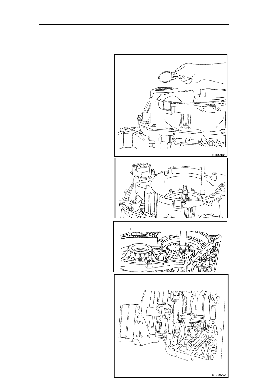
depth is determined
the
uter racer and the
case plane is 10.2mm. The distance
from the odometer drive gear case
to the bolt hole surface is 8.65mm.
The washer is 1.65mm thick;
63. Install the converter case and
washer and fix them with bolts:
The bolts’ tightening torque:
23Nm
64. Use the transmission fluid to
lubricate clutch B drum.
Tighten the adjusting bolt on
the brake band with a
tightening torque of 10Nm.
Note: Rotate clutch B drum while
tightening the brake band to ensure
that it is installed to the correct
position;
65. Turn the adjusting bolt
counterclockwise by 3mm.
Note: The gap between the
adjusting bolt and brake band is
.9mm~1.2mm;
62. In accordance with the measurements, install one or two washers between the differential and
the odometer drive gear case. Adopt the combination of different depths in order to get the
most approximate value. The
washer’s
by the following formula:
S=A-B+0.1mm
For example: The distance between
bearing’s o
The washer’s thickness is S:
S=10.2-8.65+0.1=1.65mm;
0