Chery SQR 7160 sedan. Manual - part 47


  Index      Chery     Chery SQR 7160 sedan - service repair manual


Search            


Content   ..  45  46  47  48   ..


Chery SQR 7160 sedan. Manual - part 47


CAC Gasoline Engine Maintenance And Servicing Manual 

106 

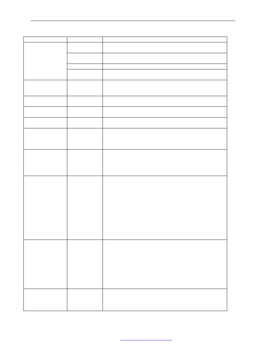
5.malfaction, cause and correction 

Malfuction 

cause 

Correction 

Fuel  pump.  fuel 
injector IVM523 

check for operation by CHECK—UP1   

Tachometer 
senser. 

Check wring, sensor resistance and installation of    the sensor. 

Dual relays 

Check for function, connector connection and blown fuse. 

Vehicle cannot start 

35——pin 
connection 

Check for the wiring connection to ECU. 

Difficult to start; 

idling    speed    too 

high or too low 

Engine 

idling                                                                                                                                                                                                                                                                       

speed 

control 

solenoid. 

check  for  solenoid  operation  and  4—pin  connection  by 
CHECK—UP1.   

warning light on 

During idling, 

λsensor 

Check  for  the  wiring,  proper  sensor  tightening  torque  and  the 
sensor heater’s operation 

warning light on for 

a long time 

Diagnosis 
warning light 

Check for the signal wiring grounding. 

warning light 

doesn’t turn on 

Diagnosis 
warning light 

The bulb is broken or circuit is open 

Rough idling at high 

temperature. 

Throttle 

valve 

sensor  or  water 
temperature 
sensor 

the  throttle  valve  opening  angle  and  water  temperature  signal 
displayed by CHECK—UP1 should match the engine operation. 

Rough idling at low 

temperature. 

coolant 
temperature 
sensor  or  intake 
air  temperature 
sensor 

The  temperature  indicated  should  be  in  the  vicinity  of  the 
ambient temperature. 

Idle intermittent 

wave 

1—throttle 
  valve body 
  30MM4 

1.check  the  throttle  valve  cable  for  proper  adjustment,  smooth 
movement. 
2.if  the  throttle  valve  cable  is  correctly  adjusted  and  may  move 
smoothly,    remove it. Check the throttle valve for resistance by 
turning it with a hand (for friction); 
3.display the throttle valve position by CHECK—UP1. If both 1 
and  2  are  correct  and  engine  speed  is  still  high  ,  while 
CHECK—UP1  displays  “angle  is  greater  than  the  allowable 
angle”,  then  the  malfunction  is  positively  determined.  It  is 
necessary to replace the throttle valve potentiometer. If the angle 
is within the specified range, sensor wiring and connector should 
be checked. 

Idling speed 

fluctuates 

continuously at high 

temperature. 

1.throttle valve 

  body 

1.2 seal 
1.3 

vacuum 

  connection


1.  check  the  above  item  1,2,3  for  intermittent  idling  speed 
functions; 
1.2 check the seal between cylinder head and throttle valve body; 
1.3check  the  vacuum  lines  to  the  two  vacuum  passages,     
which  are  of  absolute  pressure.  check  the  fuel  vapor 

recirculation

  passages,  which  are  connected  to  the  throttle 

valve body and intake manifold. 
    Check  the  vacuum  tube  sealing  in  intake  manifold  for  brake 
servo . 

Vehicle performance 

deteriorates 

1—fuel  supply 
system 

1. Check for fuel supply. If fuel pressure is 1±0.1bar,    it is ok; 
2.  If  malfunction  still  remains  after  upper  throttle  body 
(30mm12)  is  replaced,  with  a  pressure  regulator  in  the  upper 
throttle body, check fuel filter and fuel pipes. 

PDF 文件使用 "pdfFactory Pro" 试用版本创建  


www.fineprint.com.cn

CAC Gasoline Engine Maintenance And Servicing Manual 

107 


PDF 文件使用 "pdfFactory Pro" 试用版本创建  


www.fineprint.com.cn


····································································································································

··································································

·························································································

···················································································

············································································

 Index  

FORWORD 

1、Automatic transmission (A/T) assembly description

1.1、4HP14 A/T assembly explode view

1.2、Transmission Power transfer schematic

1.3、Adjusting automatic transmission clearance

1.3.1、Adjusting s

hift shaft clearance

····························································································

···························································································

·········································································

························································································

······························································································

·························································································

························································································
························································································

······································································································

····························································································································

···························································································

························································································

·····················································································

········································································································

······································································································

·················································································································

·······································································

····················································

················································································································
················································································································

················································

·····················································································

································································

·························································································

····································································

········································································································

························································

······················································································

······································

··········································································

··································································································

·····················································

·····································································

············································································································

·······························································

1.3.2、Adjusting output gear clearance

1.3.2.1、Adjusting main rear output gear clearance

1.3.2.2、Adjusting driven shaft clearance

1.3.3、Adjusting clutch A clearance

11 

1.3.4、Adjusting central seat clearance

12 

1.3.5、Adjusting differential pretension

14 

1.3.6、Adjusting brake band pretension

16 

1.3.7、Adjusting throttle cable

17 

1.4、Special tool

18 

1.5、Transmission bolt tighten torque

30 

1.6、General inspection of transmission

31 

2、Disassembling automatic transmission

32 

2.1、Disassembling assembly

32 

2.2、Removing band brake C 

43 

2.3、Removing brake D

44 

2.4、Removing central seat, brake C and oil pump

45 

2.5、Removing clutch B and 2nd gear one-way overrun clutch

48 

2.6、Removing clutch A

49 

2.7、Removing clutch E

51 

2.8、Removing output shaft and 1st gear one-way overrun clutch

52 

2.9、Removing governor and speedmeter

54 

2.10、Removing transmission case and parking system

58 

3、Assembling automatic transmission

64 

3.1、Installing transmission case and parking system

64 

3.2、Installing band brake C’

74 

3.3、Installing brake D and 1st gear one-way overrun clutch

78 

3.4、Installing governor and driven shaft

82 

3.5、Installing planetary gear mechanism and main sub rear output gear

86 

3.6、Installing input shaft and clutch E assembly

93 

3.7、Installing clutch A assembly

96 

3.8、Installing clutch B and 2

nd

 gear one-way overrun clutch

100 

3.9、Installing centeral seat, oil pump and brake C assembly……………………………………103 
3.10、Insatlling differential and converter housing

109 

3.11 Installing speedmeter

112 

3.12 Installing control valve plate and torque converter

115 


Appendix 

The manual of 4HP14 A/T removing & installing                                                                CHERY AUTOMOBILE CO., LTD 

FOREWORD 

This manual covers 4HP14 automatic transmission (A/T) repairing methods, detailed A/T removing & 

assembling procedures and information on determining if a transmission needs repairing upon problems.


In addition, we recommend as followings: 

1、Throttle cable, gasket, O ring, shim and other vulnerable parts must be replaced after removing. 

2、After over 31,250 miles or 50,000 km mileage, all clutches and brakes must be replaced. 

3、If the clutch is bumped, it is absolutely necessary to use appropriate cleaning agent to clean torque converter, 

oil cooler and oil cooling chamber. 

4、When installing transmission, any adjustment should be made according to instructions in section 1.4 of the 

manual. 


Removing and installing requirements: 

1. Use transmission repairing special tools listed in section 1.8 in this manual. 

2. Appropriate test bench. 


NOTE: 

1. Valve body must be repaired by professional person; 

2. Valve body must be replaced as an assembly; 

3. Transmission oil must be filled as specification. 


-1-


Content   ..  45  46  47  48   ..