Chery SQR 7160 sedan. Manual - part 43


  Index      Chery     Chery SQR 7160 sedan - service repair manual


Search            


Content   ..  41  42  43  44   ..


Chery SQR 7160 sedan. Manual - part 43


CAC Gasoline Engine Maintenance And Servicing Manual 

90 

 
        When  ECU  microprocessor  identifies  the  signals  of  two  tooth-missed  signals  ,  it  will  begin  to    count 
tooth. cylinder 1 or cylinder 4 TDC comes after 20 teeth are counted .cylinder 2 or cylinder 3 TDC comes after 
50 teeth are counted (determine by pair). 

ECU  calculate  the  primary  coil  conductivity  of  cylinder  1,  4  or  cylinder  2,  3  and  ignition  advance 

according to the  gained parameters (pressure, rpm) and calculate the  dynamic compensation according to the 
engine working condition. 


        the following is for checking primary coil and secondary coil    resistance. 
        R1=0.55Ω+/-10%    (20℃)          R2=7400Ω+/-10%    (20℃) 
        The  base  ignition  advance  value  in  the  chart  is  determined  after  several  adjustments  according  to  the 
coolant  temperature  and  air  temperature.  one  filter  restricts  the  change  of  two  continuous  TDCs,  Under  a 
specified condition, ignition advance will be compensated dynamically.   
        Base ignition advance value ,as a function of manifold absolute pressure and engine speed, is inserted into 
two-dimension diagram . 
        At  a  rather  low  speed,  ignition  advance  remains  fixed.  The  positive  and  negative  change  of  ignition 
advance between two continuous TDCs is limited by two calibration values. 
        The dynamic compensating of ignition advance occurs under the following conditions: 
        —— during idling or running without rpm fluctuations 
        —— during acceleration and deceleration shut 
        —— when shutten off 
        —— during over speeding 
        during  idling,  the  engine  rpm  is  900±50r/min,and  ignition  advance  is  10°±1°(Engine  is  already 
warmed and with no electrical load). 


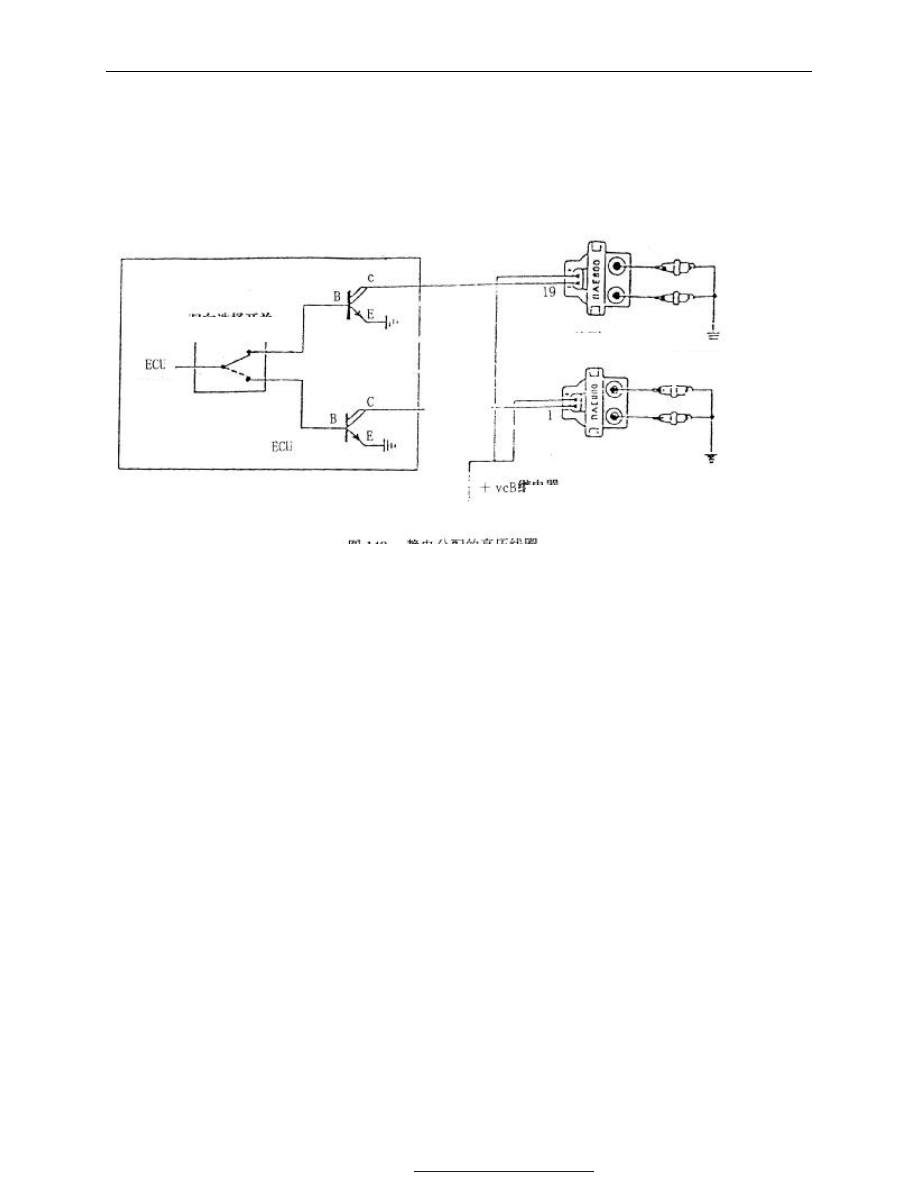
Fig. 149 high pressure coil of electrostatic distribution 
 

two-way select switch 

coil 

relay 

signal 

Spark plug 

PDF 文件使用 "pdfFactory Pro" 试用版本创建  


www.fineprint.com.cn

CAC Gasoline Engine Maintenance And Servicing Manual 

91 

 
6 zirconiumλ  sensor is designed to detect the oxygen in exhaust emission 
        In  endothermal  engine,  the  combustion  is  produced  by  the  reaction  of  hydrogen  and  oxygen  and  then 
emits  heat.  Fuel  is  composed  of  hydrocarbons.  It  includes  carbon  atom  and  hydrogen  atom  which  are 
combined together by different modes (paraffin, olefine, aromatics). 
        The  main  products  of  the  air  and  fuel  combusting  are  carbon  dioxide  (CO

2

),  vapor  (H

2

O),  carbon 

monoxide (CO) and a small percent of unburned hydrocarbon (HC) and nitrogen oxide (NO

X

). The last two are 

measured by ppm. 
        For the pollution problem, only carbon monoxide exists largely in the form of bulk. 
        Nitrogen oxides is composed of the oxidized mixture. The main ingredients are as following: 
        dinitrogen oxide, nitrogen monoside (NO), nitrogen dioxide 
        NO

X

 is the traditional symbol for these oxide. NO covers over 95% of them. 

        In order to minimize pollution (CO、HC and NO

X

),

“λsensor”  is installed into the system to detect the 

oxygen content    in exhaust emission. 
        The signal coming from the sensor is sent to ECU for adjusting the mixing ratio of air and fuel, ensuring 
the catalytic converter work under the optimal condition. 
        The sensor is located in the first section of exhaust pipe, in front of the catalytic converter. 

It is enclosed by ceramic zirconia body (1) with thin platinum plate at one end. The latter one is inserted 

in a protecting boot and installed in a metallic body (3). The protective casing works for the further protection 
and has the sensor in the exhaust manifold.   


        The  outside  of  the  ceramic  body(b)  is  exposed  to  the  exhaust  emission  and  the  inside  (a)  is  exposed  to 
ambient atmosphere. The working principle of sensor is as following: When the temperature is over 300℃,the 
ceramic  material  will  be  the  conductor  of  ferric  oxide.  Under  this  condition,  if  the  percentage  content  of  the 
oxygen in the two sides of sensor (a, b) are not the same, the voltage difference will occur in the two sides. The 
difference of measured oxygen content in two ambient (at the side of air and at the side of exhaust) tells ECU 
that the remainin  oxygen content in the exhaust is not  propriate for ensuring the combustion with  no  harmful 
exhaust products produced   
        The ceramic material under 300℃  is non-linear, therefore the sensor doesn’t send the useful signal. ECU 
has a special function, i.e. stop adjusting the mixture during engine warming (open loop operation). 
        the  sensor  is  equipped  with  a  heating  unit  (4)  to  reach  the  operation  temperature  as  soon  as  possible. 
When the current flows over the heating unit, it shortens the time for ceramic becoming the conductor of iron 
and may have the sensor installed in the relatively rear area of exhaust pipe. 
λsensor inspection: 

Fig. 150 oxygen sensor 

PDF 文件使用 "pdfFactory Pro" 试用版本创建  


www.fineprint.com.cn

CAC Gasoline Engine Maintenance And Servicing Manual 

92 

        to  check  all  sensors  and  actuators,  injection  system  ECU  has  a  complete  high-efficiency  self-diagnosis 
system. When failure occurs, the warning light will turn on.   
        Warning:Before checking exhaust emission orλsensor, check: 
        1. The  warning  light  should  go  out,  or  use  CHECK—UP1  diagnosis  instrument  to  determine  the  failure 
and adjust it for correct operation. 
        2. little difference exists between the working parameter showed on CHECK—UP1 and the actual engine 
condition. 
        3.  The  fuel  pressure  should  be  the  specified  value  (0.9—1.0bar).  When  the  pump  stops,  no  sudden 
pressure drop occurs ( pressure sealing). 
        4. When the fuel pump operates, CHECK—UP1 performs to stop engine and recycle oil circuit.   
 

Injection  system  ECU  may  adjust  automatically,  therefore  it 

may  compensate  for  the  system  failure  caused  by  the  engine 
degradation. According to the signal of  λsensor (figure 151),in 
the precondition  of  without any exterior interference, the  mixture 
can be automatically adjusted to the perfect value electronically. 

·When  engine  is  idling  with  no  electrical  load  and  λ

controlling is functioning(close loop),select LAMBDA CHECK 
to check if the slipping ruler on the CHEC K—UP1 diagnosis tool 
is in the middle of two base points . 


7 catalytic converter 


Exhaust emission is controlled by  λsensor and the above relative systems and three-way catalytic converter. 

Fig.151 λ sensor signal   

drawing 152 exhaust system
1.  λsensor    2. catalytic converter
3.  CO  inspection  channel,  in  front  of 
catalytic converter 
 

PDF 文件使用 "pdfFactory Pro" 试用版本创建  


www.fineprint.com.cn

CAC Gasoline Engine Maintenance And Servicing Manual 

93 

Catalytic  converter  may  damp  the  three  contaminations  in  the  exhaust:  unburned  hydrocarbon  (HC),  carbon 
monoxide(CO) and nitrogen oxide (NO

X

). 

        two  kinds  of  complicated  chemical  reactions  exist  in  the  catalytic  converter:  the  oxidation  of  carbon 
monoxide and hydrocarbon changing into carbon dioxide and water; nitrogen oxide changing into nitrogen.   
        note:Using leaded gasoline may damage the catalytic converter and weaken its catalytic capability so that 
it does not function completely for the system. And the damage is irremediable. The weakening of the catalytic 
converter capability for the chemical reaction should not occur within 80 thousand kilometers or five years.   
        Besides lead, the unburned fuel in the converter is another factor for the catalytic converter failure.   
        In the catalytic converter, the temperature is 800℃. Even so,if fuel only remains in the converter for 30 
seconds , the combustion caused by the fuel will damage the converter .sometimes,    a few-second stay of the 
fuel in the converter    may result in irremediable damage. Therefore, it is very necessary to insure the ignition 
system high performance. 

during repairing and testing, be sure to avoid unplugging the spark wire when engine is operating. If it is 

needed to do this kind of test, it is suggested to replace the converter temporarily with a pipe and perform the 
test.   


1. fuel tank (with sealing fuel tank cap)                2. Two-way check valve 
3. injection/ ignition (ECU)                                    4. Multi-function valve 
5.charcoal canister(in the engine compartment)    6. fuel vapor recirculation solenoid 
7.throttle valve body 

8. Expansion chamber 

the  fuel  tank  ventilation  style  applied  on  the  system  is  “close  loop”  type.  It  prevents  the  vapor  coming 

from the fuel tank and fuel supply system from emitting into the atmosphere. thus the small quantity of carbon 
compound in the fuel vapor is prevented from emitting and polluting the atmosphere    . 

The operation during engine doesn’t run (figure. 154) 

Fig.153 part position of anti-fuel vaporization system 
 

PDF 文件使用 "pdfFactory Pro" 试用版本创建  


www.fineprint.com.cn


Content   ..  41  42  43  44   ..