Chery SQR 7160 sedan. Manual - part 41


  Index      Chery     Chery SQR 7160 sedan - service repair manual


Search            


Content   ..  39  40  41  42   ..


Chery SQR 7160 sedan. Manual - part 41


CAC Gasoline Engine Maintenance And Servicing Manual 

82 

The following accessories and engine air filter are installed on the upper body of throttle valve. 
·fuel system pipe and fuel return pipe 
·fuel pressure regulator 
·bottom-supplying fuel injector IWM 
·intake air temperature sensor. 


——Fuel pressure regulator 
As  engine  is  running,  fuel  pump  supplies  fuel    (fuel  supply  volume  of  pump  is  about  80L/h)  through 

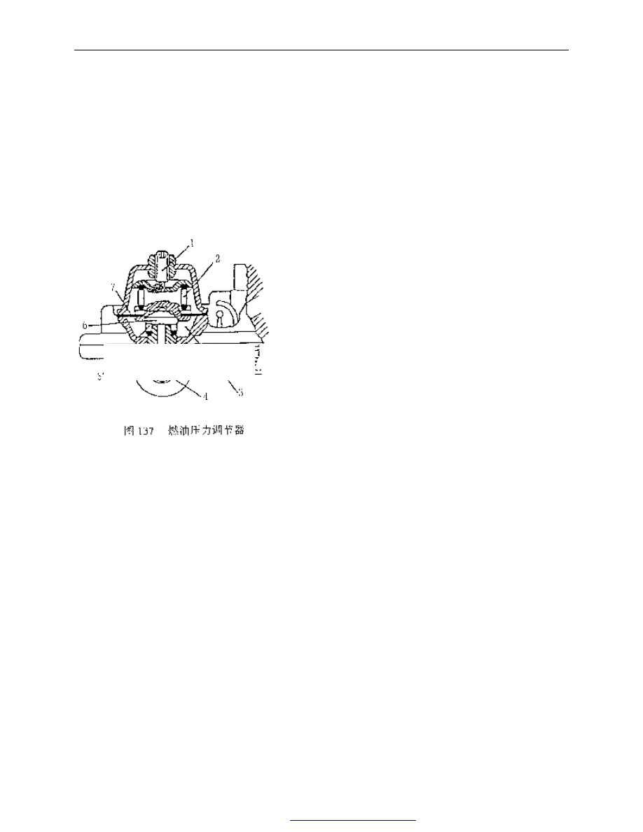
filter  and  pipe  to  fuel  pressure  regulator(chart  137).  The  regulator  is  designed  to  keep  the  specified  fuel 
pressure at 1bar(0.9-1bar), and redundant fuel will recirculate flowing into fuel tank. Fuel will clean and cool 
injector during recirculation. 


——working procedure of Fuel pressure regulator . 

Spring (2) applies pressure on the diaphragm(7) connected 

to  sealing  valve(6)    keeping  cavum  closed  between  fuel 
delivery pipe and fuel return pipe(4). 

whe  fuel  pressure  in  pipe(3)  exceeds  1  bar  ,  pressure  on 

diaphragm(7)  will  overcome  spring(2)  resistance,  then 
diaphragm  goes up raising sealing  valve up to allow redundant 
fuel to flow back and returns to proper work pressure. 

during  producing,  fuel  pressure  regulator  pressure  is 

calibrated  by  socket  head  bolt  and  will  never  changed  under 
any circumstance. 

——Fuel 

injector 
1.  socket head regulator screw 
2.  spring 
3.  fuel output pipe 
4.  fuel return pipe 

5.  spring 
6.  sealing valve 
7.  diaphragm 


Fig.137 fuel pressure regulator 

PDF 文件使用 "pdfFactory Pro" 试用版本创建  


www.fineprint.com.cn

CAC Gasoline Engine Maintenance And Servicing Manual 

83 

IWM523 fuel  injector applied in the system is  of the shortened type  of the first  generation. It  is entirely 

made of stainless steel and superior in the function.  The  advantage  may be  embodied    when the  commercial 
fuel  containing  corrosive  material  is  applied.  figure  138  shows  fuel  injector  structure  and  some  technical 
parameters. 

Technical parameters: 

-winding resistance 
R=1.8Ω+/-10%(20℃) 
-power supply voltage 
V=6-16V 
-spraying shape 
angle 30~90° 
-operating temperature 
-30~+110℃. 


when  fuel  injector  is  not  operating,  it  is  sealed  and  doesn’t  allow  fuel  drain.  Fuel  needed  by  engine,  is 

controlled by ECU(supplied  electricity by relay (87))directly. And ECU  decides the  open time of each intake 
order and fuel injection duration. 

Fuel injection time is controlled by the following measures: 
-synchronous(for normal operation) .injector opening corresponds with every TDC. 
-not  synchronous    (for  idling,  cut-off,  low  speed,  start  operation).injector  opening  is  completely 

controlled by time and not related to TDC signal. 

ECU  has  a  basic  current  control  circuit  to  control  fuel  injector.  The  circuit  produces  the  maximal 

current(signal) at the first control order speed up the  opening of injector. Once  maximum  current is attained , 
the circuit will automatically change to and keep the current I=1A±0.3 A(Mean). 

Injection duration is showed on the 2-dimension figure as a function of engine speed and intake manifold 

absolute pressure . After engine warming up or speed turns to be stable, injection duration is 1~4mS. 

Injection  duration  is  increasing  basically  under  special  operation  condition,  such  as  accelerating,  cold 

starting, engine warming up. As accelerator pedal is released, fuel will be cut off.( ti=0mS). Running condition 
and readjusting condition may be changed according to water/ intake air temperature or A/C condition. 

——intake air temperature sensor  “ATS05” 
It is consisted of N.T.C.(Negative Temperature Coefficient) thermo resistance and 2-way junction box that 

are installed in the plastic setting molding case. Sensor resistance will changed with intake air temperature. 


Fig. 138 fuel injector   

+12V relay 

ECU 18 insert pin 

PDF 文件使用 "pdfFactory Pro" 试用版本创建  


www.fineprint.com.cn

CAC Gasoline Engine Maintenance And Servicing Manual 

84 


2.2  Lower body(air system)—description and function of accessories   
Excepted  that  connecting  throttle  valve  to  accelerator  pedal  by  a  lever,  the  following  parts  should  be 

installed on the lower body. 

·throttle valve position sensor 
·stepper motor 
·hot water loop near the throttle valve and idle air by-pass 
·absolute  pressure  signal  port  in  the  lower  throttle  valve    (necessary  to  be  connected  with  pressure 

sensor) 

·PCV recirculation pipe   
 
——throttle valve position sensor “PF2C”. 
figure  140  shows  the  position  sensor  case  structure  ,also  the  relationship  between  output  characteristic, 

output signal and throttle valve opening ange. 


·Sensor component is consisted of a potentiometer. The slipping ruler of potentiometer is driven directly 

by accelerator pedal which is proportional with throttle valve opening. 

·the potentiometer is inserted into plastic case with two baffles on the bracket. There are two   

Fig.139 temperature sensor and principle 

water 

Air   

Connecting chart   

Fig. 140 throttle valve position sensor and operation chart 

ground 

Signal output 

power 

throttle valve opening(angle) 


PDF 文件使用 "pdfFactory Pro" 试用版本创建  


www.fineprint.com.cn

CAC Gasoline Engine Maintenance And Servicing Manual 

85 

holes in the bracket for installing the potentiometer on throttle valve. 

·  there is spline on the shaft. the spine provides data about throttle position. The data is used to confirm 

idle operation condition(accelerator pedal released), full load(accelerator pedal depressed) and accelerating or 
decelerating conditions. 

·  with absolute pressure sensor out of work, the position sensor will function when working condition 

comes back. 

·ECU  supplies  5V  voltage  to  the  variable  resistance  terminal    of  throttle  valve  potentiometer  .  And 

potentiometer output voltage varies with throttle valve position. 

·sensor needs not adjustment(through assembling hole), for ECU program may self adjust to minimum 

impedance(2°to 14°).   

Warning——the following order should be taken during potentiometer replacement: 
1.  tighten mounting bolt on the new potentiometer. 
2.  turn  ignition  key  to  the  MAR  before  connecting  line  to  the  potentiometer,  and  wait  for  several 

minutes. 

3.  turn ignition key to Stop. 
4.  connect wire to the potentiometer’s insert hole. 
5.  insert CHECK-UP1 tester. Turn ignition key to CN and erase trouble display. 
6.  keep connection until throttle valve position displayed on the screen is 2°~14°. If the parameter is 

above 14°, you should check throttle cable and make sure it’s correct (not very tight). Or it needs to 
be adjusted again. 

Notice:  Don’t  adjust  the  potentiometer  bolt  if  it  does  not  return  to  the  specified  value  of  throttle  valve 

opening angle. The potentiometer should be replaced because it fails. 

 
——engine idle speed actuator(idle control stepper motor) 
Idle control stepper motor is a position actuator of high precision and high distinguishability( +/-50r/min) 

for controlling idle speed. 

It is consisted of stepper motor and screw rod-type reduction gear. The reduction gear    converts the valve 

rotating  into  linear  movement.  Stepper  motor  receives  the  signal  from  ECU  and  makes  valve  shaft  move  by 
screw rod changing air by-pass passage(see figure 8). Then engine air intake will change during idling. It will 
vary with coolant water temperature  whether air intake is increasing  or decreasing, which  keeps speed stable. 
Engine  minimum  idle  air  intake  is  set  by  adjusting  throttle  valve  opening  when  by-pass  channel  is  closed 
completely.    Be  sure  not  to  touch  mixture  adjustment  bolt.  Engine  maximum  idle  air  intake  is  set  by  valve 
returning  position  ,  i.e.  about  200  steps  (8mm  travel).  The  operation  steps  is  the  function  of  engine 
conditions(preheating cycle, electrical load, A/C working condition, engine running (hot)). 


PDF 文件使用 "pdfFactory Pro" 试用版本创建  


www.fineprint.com.cn


Content   ..  39  40  41  42   ..