Chery SQR 7160 sedan. Manual - part 36
CAC Gasoline Engine Maintenance And Servicing Manual
62
2.2 PCV valve’s function:
under the low speed condition, the vacuum of intake manifold
is very high, which keep the valve closed, and only a small opening
exists to allow the gas pass through. Therefore it won’t change the
mixture rate. Under high speed condition, the vacuum of intake
manifold decreases, and the spring forces the valve to open to allow
more gas in the crankcase flow into intake manifold.
the PCV valve is designed to open fully enough to allow the
gas exhaust from the crankcase under high speed or low speed
conditions.
【17】. Fuel supply system of the carburetor engine.
1.
Fuel supply system of the carburetor engine.
1.1 Description
of
the
fuel
supply system.
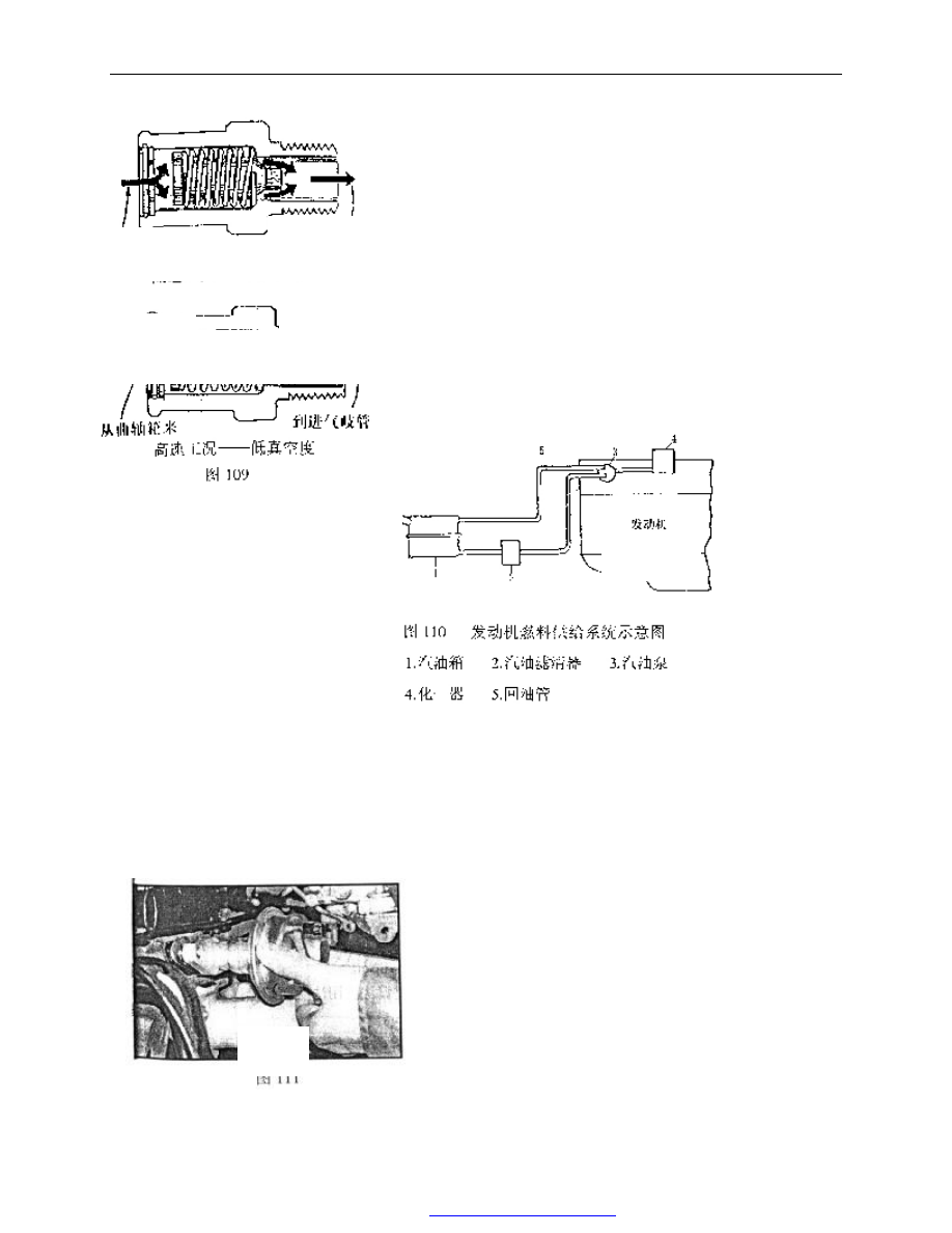
The fuel in
the tank flows
into oil filter
pumped by the
fuel pump and
goes
into
carburetor after
being
filtered
through
fuel
pump
.
A
amount of fuel
returns to the
tank
through
return pipe .
1.2 Removal and assembly of the fuel pump:
——Remove two M8 lock nuts.
——Take out the fuel pump.
——Remove the fuel pump sealing gasket.
——pull out the push rod.
From crankbase
From crankbase
the operation condition of low speed-high vacuity
to intake manifold
the operation condition of high speed- low vacuity
Fig.109
to intake manifold
Engine
Fig.110 schematic drawing of fuel supply system for engine
gasoline filter 3. gasoline pump
Fig. 111