Chery SQR 7160 sedan. Manual - part 34


  Index      Chery     Chery SQR 7160 sedan - service repair manual


Search            


Content   ..  32  33  34  35   ..


Chery SQR 7160 sedan. Manual - part 34


CAC Gasoline Engine Maintenance And Servicing Manual 

54 

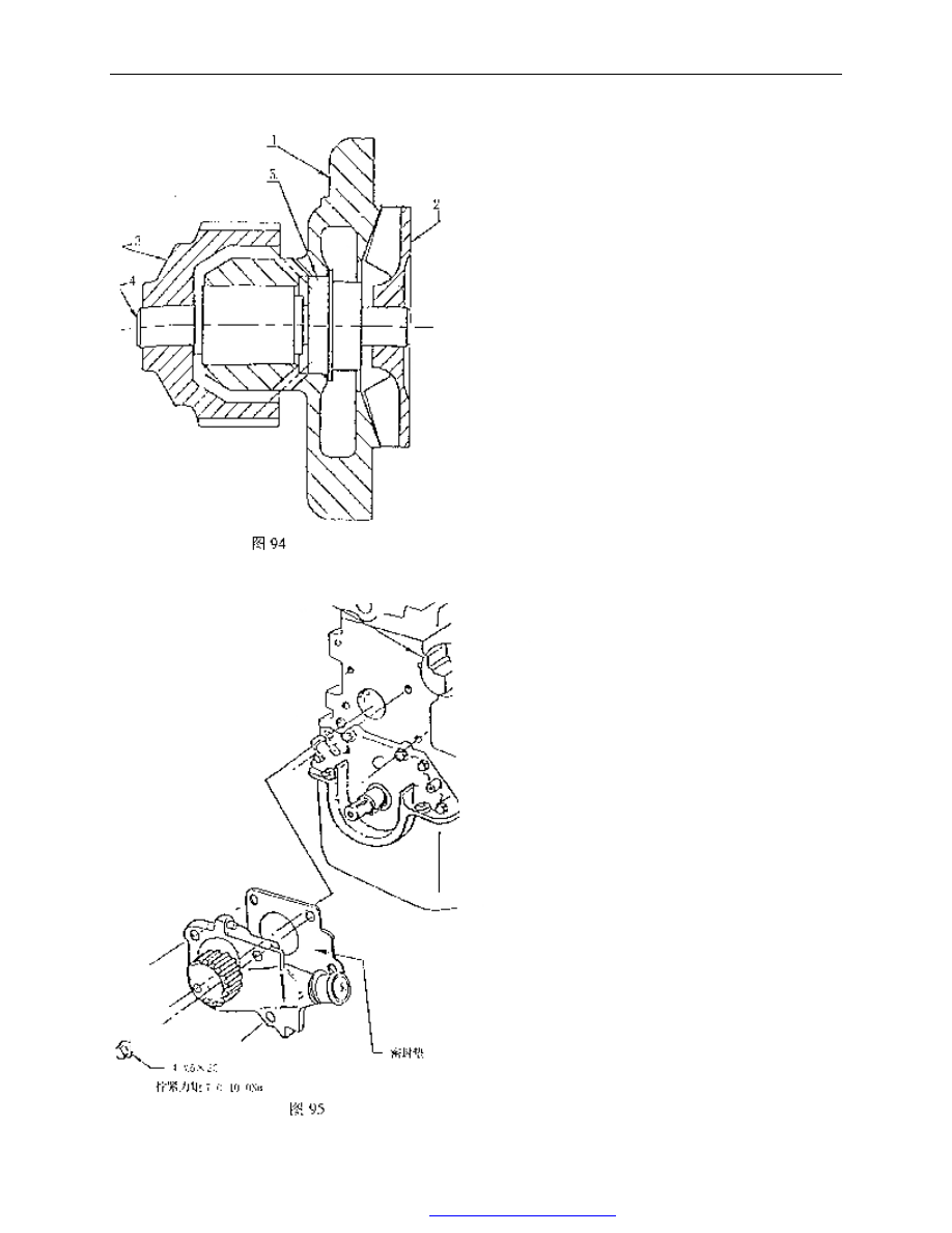
2)  The  removal  and  installation  of  water  pump 
assembly 
——The structure of water pump assembly 
            1—water pump case 
            2—water pump impeller 
            3—water pump gear 
            4—water pump bearing 

5—water pump seal (ceramics—black lead) 


Removal: 

——Loosen and remove four bolts from the 
front    end of cylinder block 
——Remove water pump assembly 
——Remove sealing gasket of water pump 
 
Installation: 
——Install  new  sealing  gasket  of  water 
pump on the water pump 
——Install the water pump assembly inside 
the  cylinder  block  and  screw  in  four 
retaining  bolt  by  hand,  then  tighten  to 
7.0—10.0Nm. 
 
Note: The water pump assembly may not be 
serviced.  When  water  seal  or  bearing  is 
damaged,  the  water  pump  assembly  should 
be replaced 
 

Fig. 94 

Tighten torque 

Sealing plate 

Fig. 95 

PDF 文件使用 "pdfFactory Pro" 试用版本创建  


www.fineprint.com.cn

CAC Gasoline Engine Maintenance And Servicing Manual 

55 

3) The removal and installation of thermostat seat with thermostat assembly   


——Loosen three M6×40 bolts and remove them 
——Remove thermostat seat with thermostat assembly 
——Pry out spring clip by chisel or screwdriver 


——Take out the thermostat 


——Take out sealing gasket 
——Remove sealing gasket of thermostat seat 


Measure the opening temperature of thermostat in hot water.   


Fig.96 

Fig. 97 

Fig. 98 

Fig. 99 

PDF 文件使用 "pdfFactory Pro" 试用版本创建  


www.fineprint.com.cn

CAC Gasoline Engine Maintenance And Servicing Manual 

56 


Assembly: 

——Clip the thermostat seat, and put the rubber seal ring into the thermostat hole. 
——Install the thermostat(with spring outward) 
——Install spring clip, ensure that the clip is clipped in the thermostat seat groove. 
——Install the sealing gasket of the new thermostat seat on the thermostat assembly with a bolt. 
——Install the thermostat together with thermostat assembly into the rear end  hole  of cylinder  head. Finger 

screw in 3 bolts and tighten to 9-12Nm. 

——Tighten the hex head plug with the sealing gasket on . tightening torque is 38-42Nm. 
——For  the  engine  equipped  with  electrical  heater  ,install  air  intake  preheating  switch  .tightening  torque  is 

38-42Nm. 

3. removal and assembly of the water temperature sensor. 
Removal: 
——Remove the water temperature sensor(at the exhaust    side , under the rear lug). 

Assembly: 

——Before  installation,  apply  the  lotite  sealant  243  onto  the  bolt  threads  .finger  screw  in  and  tighten  to 

7.0-10.0Nm . 

 
15】: The intake and exhaust system of the engine. 
1.  Description for the intake and exhaust system of carburetor engine. 
The intake system of Carburetor Engine 478 and 480 includes: air filter, Intake hose, Guide cover, Carburetor, 
Intake hose, Intake air preheating hose of Positive Crankcase Ventilation(PCV), and so on. 
——air filter type is 1GD129607G, and its basic parameters are as the following: 
Filtering area: 100cm2              nominal air flow(L): 600±150           
filtering efficiency:  ≥99%        filtering resistance: 2kPa 

thermostat 

Sealing gasket 
 

Overflow pipe 

Drainage pipe 

Sealing gasket 

Small recircula- 

ting pipe


Plug screw 

Spring clip 

Sealing gasket 

Tighten torque 

Fig.100 

Temperature seat assembly 

PDF 文件使用 "pdfFactory Pro" 试用版本创建  


www.fineprint.com.cn

CAC Gasoline Engine Maintenance And Servicing Manual 

57 


——The air filter is equipped with a intake air temperature controller. When the temperature is low, the hot air 
intake valve controlled by the temperature controller will open and the hot air, flowing by the exhaust manifold, 
will be directed into the air filter from the intake preheating hose to supply more hot air and facilitate the fuel 
atomization during cold winter. As temperature is high , valve is shutted off and the hot air is not permitted to 
enter the air filter. 
——Carburetor(see Fuel System) 

The  exhaust  system  of  the  carburetor  engine  478  and  480  includes  Exhaust  Manifold,  Heat  Insulation 
Cover, Exhaust Hose, Front Muffler, Rear Muffler. 
 

2. Description for the Exhaust System of Engine 2.480M: 


The  Intake  System  of  Engine  480M  includes:  air  filter,  Intake  Hose,  Guide  Cover,  Throttle  Valve,  Intake 
Manifold, Intake air preheating hose of Positive Crankcase Ventilation(PCV)and so on. 
——Air filter type is 1GD    129    607G, and its basic parameters are as follows: 

Filtering area: 100cm2              nominal air flow(L): 600±150 
filtering efficiency:  ≥99%        filtering resistance: 2kPa 

Fig. 101 intake and exhaust system arrangement of carburetor engine 
 

Intake hose 

guide cover 

carburetor 

Air filter 

Intake preheat hose 

exhaust manifold 

intake manifold 
 

Exhaust hose 

engine 

front sound absorber    back sound absorber 
 

Fig.102 intake and exhaust system schematic drawing of engine 480M 
 

3 way catalyst 

front sound absorber    back sound absorber 

flexible hose 

Oxygen sensor 

Exhaust hose 

engine 

Intake hose 

Air filter 

guide cover 
 

throttle valve 

Intake preheat hose 

insulating 
cover 

cylinder 

cap cover 

intake manifold 
 

PDF 文件使用 "pdfFactory Pro" 试用版本创建  


www.fineprint.com.cn


Content   ..  32  33  34  35   ..