Chery S11 / Chery QQ. Manual - part 268
 

  Index      Chery     Chery S11 / Chery QQ - service repair manual


Search            


Content   ..  266  267  268  269   ..


Chery S11 / Chery QQ. Manual - part 268


Chery    QQ    Maintenance Manual                      Transmission System


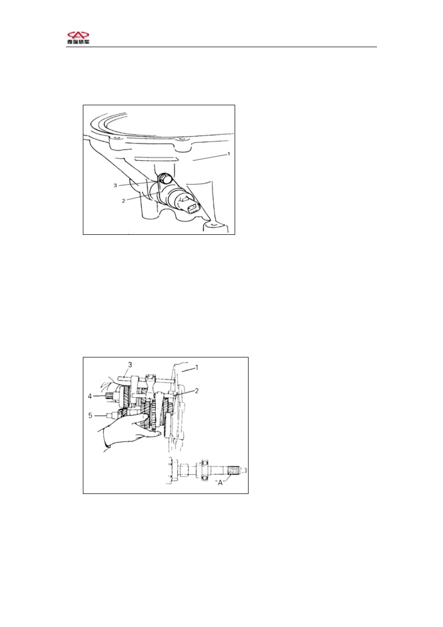
2、Spread lubricant on the “O” ring and gear, install the speedometer driven gear 

assembly,and then screw down the torque.     

Torque:8~12 N·m 


1-Clutch case 

2-Speedometer driven gear

assembly 

3-Bolt


                 Fig.3-65 

Notice: When installing speedometer driven gear, turn the differential    ring driven 
gear lightly to joggle the gear. Do not knock the cracks on the speedometer case, 
otherwise the    case may be broken. 

3、Hold the input shaft assembly、output shaft assembly、1st、2nd shift  fork 

assembly and 3rd、4th Shift fork assembly and fix them on the clutch case. 
Notice: Use hammer to rivet the input shaft right bearing into clutch    case。 
Be sure output shaft and differential    ring driven gear are joggled。 
Notice:In order to  protect  oil  seal,twine  the insulating tape  to input shaft 
splined  hub。 


1-Clutch case 

2-1st 、 2nd   Shift  fork

shaft assembly 

3-3rd  、 4th  Shift  fork

shaft  assembly 

4-Input shaft assembly 

5-Output shaft assembly


Fig.3-66  

4、Install the reverse shift fork, screw down the bolt。     

Torque  :18~28 N·m 

Notice:When installing the reverse shift fork, keep the distance 5mm from the end of   
shift fork and the shaft hole.   
 

-84-  


Chery    QQ    Maintenance Manual                      Transmission System


Distance“a”  :5mm 
The distance “a”is  5mm,reverse  shift  fork end and reverse idle gear  

clearance  is  1mm 。 

5、Install the reserve、5

th

 shift fork shaft assembly. 


1-Reserve 、 5thShift  fork

shaft assembly 

2-Clutch   case 

3-Reverse Shift fork

assembly


Fig.3-67 

6、Install the reverse idle gear and reverse idle gear shaft, put the mark on the 

reverse idle gear shaft (Fig. A) and the step (Fig. B) on the clutch case in order.   
Notice: 

Be sure that reverse gear gasket has been fixed on the reverse gear. 
Be sure that the distance between reverse Shift fork free is 1mm 


1-Reverse idle gear shaft

assembly  

2-Clutch case 

3-Reverse Shift fork

assembly 

4-Reverse gear gasket


Fig.3-68 

7、Clean the clutch and transmission surface, spread sealed adhesive on the 

surface of the transmission, and fix it with clutch. 

Seal Adhesive: Seal adhesive(HZ1213Q/320222 YAP02-92) 
8、Screw down the transmission bolt according to the correct torque .   
Torque:15~22 N·m 
9、Install the reverse gear shaft bolt and aluminum gasket, screw down the bolt. 
Torque  :18~28 N·m 
10、Screw down the other 3 transmission    bolt in the    clutch.   
Torque  :15~22 N·


-85-  


Chery    QQ    Maintenance Manual                      Transmission System


1-Transmissan case 

2-Clutch case 

3-Transmission bolt 

4-Reverse idle gear shaft

bolt 

Fig3-69 

11、Check-up  shift  fork shaft point spring worn. 
 

Point spring free length 

Standard 

Use Limit 

Rreserve、5th  spring(Red) 

33.8 32.7 

Spring(Green) 

33.6 32.5 

 
12、Install the shift lever shift    fork shaft ball、spring,bolt.  
Torque  :10~16 N·m 


1-Bolt 

2-Gasket 

3- Point spring(Green) 

4-Ball 

5- Point spring(Green) 

6-Reserve 、 5

th

 point spring

(Red)

Fig.3-70 

 
45th gear 
1、Hammer the output shaft left bearing outer race lightly to the position of 

bearing. 


-86-  


Chery    QQ    Maintenance Manual                      Transmission System


1-Input shaft 

2-Left bearing outer race 

3-Special tool   

Fig.3-71 

2、First put a adjust gaster on the bearing outer race and a ruler on the adjust 

gaster, use the press ruler to measure the clearance “a”(between case surface and the 
ruler)    

Clearance“a”(adjust gaster):0.08—0.12mm 
3、Repeat the above steps, choose a suitable adjust gaster and put it on the bearing 

outer race. 
Notice: Use 0.1mm Feeler gauge to determine if the gasket is suitable or not.     
 

Bearing adjust gaster 

Thickness 

0.40、0.45、0.50、0.55、0.60、0.65、0.70、0.75、

0.80、0.85、0.90、0.95、1.00、1.05、1.10、1.15 


1-Ruler 

2-Output shaft   

3-Bearing adjust gaster   

4-Bearingouter race 

5- Case   

6-Feeler gauge 


                    Fig.3-72 


-87-  


Content   ..  266  267  268  269   ..