Chery QQ6 (S21) / S12LHD. Manual - part 230


  Index      Chery     Chery QQ6 (S21) / S12LHD - service repair manual


Search            


Content   ..  228  229  230  231   ..


Chery QQ6 (S21) / S12LHD. Manual - part 230


2.2.2 Measurement of valve guide inside diameter 

Use  an  inside  micrometer  to  measure  inside 

diameter of the guide. 

Fit  clearance  between  intake  valve  stem  and  valve 

guide: 0.012~0.043mm 

Fit clearance  between exhaust  valve  stem and  valve 

guide: 0.032~0.063mm 

Note: 

If  abnormal  noise  is  generated  due  to 

serious  wear  of  valve  guide,  do  not  replace  the  valve 

guide,  because  the  assembly  technique  requirements  to 

valve guide is very strict; please replace the cylinder head 

assembly. 


2.3 Boring and grinding valve seat insert 

2.3.1  Inspection  of  fitting  surface  of  valve.  Apply  a 

circle of red lead on the valve sealing strip  and then 

gently  place  the  strip  onto  the  valve  seat  insert, 

softly and  forcibly press it down,  but  do  not turn  it. 

Take out the valve, observe if there is broken part on 

the  red  lead,  if  any,  boring  and  grinding  the  valve 

seat insert is required. 


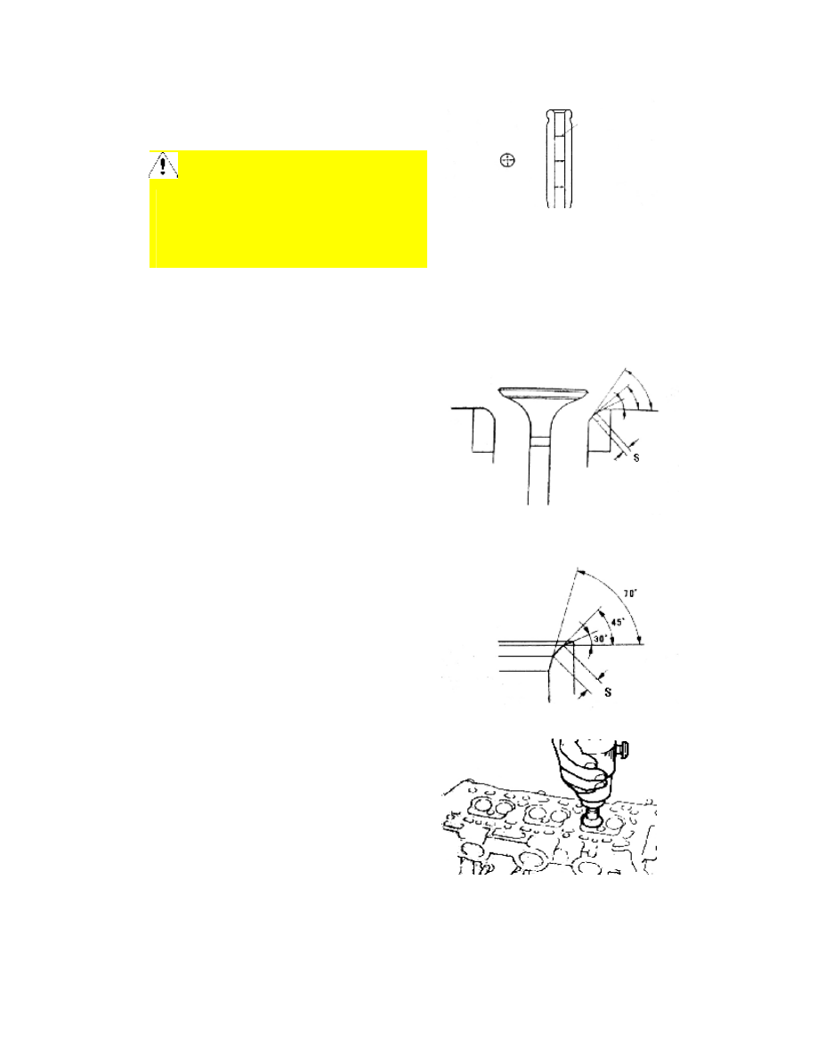
2.3.2  Select  an  appropriate  reamer,  use  45°  conical 

surface  as  cooperate  standard  value  to  check  valve 

cooperation  position:  the  optimal  position  is  the 

center  of  the  valve,  if  not  so,  be  sure  to  revise.  Cut 

on  the  conical  surface  70°  inward  and  30°  outward 

at the center of the cooperation position. 


2.3.3  Perform  seat  grinding  for  the  valve  sealing 

strip with polishing compound 


Measurement point 

2.3.4 Detection of planeness of cylinder head 

Follow  the  method  as  shown  in  the  figure  to 

measure planeness of the cylinder head with a feeler 

gauge;  the  planeness  of  the  cylinder  should  not 

exceed  0.05-0.10mm,  if  exceeding  this  valve, 

replace the cylinder head assembly. 


III. Assembly of Cylinder Head Assembly 

1.  Please  follow  the  order  adverse  to  that  for 

disassembly  of  cylinder  head  to  install,  but  care 

should  be  taken  for  the  following  matters  during 

installation. 

2.  Use  the  special  tool  CH-20012  to  install  new 

valve oil seal onto the guide first. 


3. Insert big end of the guide onto the valve guide. 


4.  Envelope  the  special  tool  onto  CH-20012,  and 

then softly and forcibly compact. 


5.  Use  a  hammer  to  knock  the  valve  oil  seal 

installation  tool, when  a  metal crash  sound is heard, 

take out CH-20012. 


6.  The  methods  for  installation  and  assembly  of 

valve spring are the same. Then install valve, spring, 

keeper,  top  barrel  and  rocker  arm.  (when  installing 

the top barrel, add a little engine oil into the hole). 


7. Install camshaft  and camshaft bearing shell cover 

assembly. 


Note: 

When  installing,  remember  to  differentiate  intake 

camshaft  from  exhaust  cam.  The  intake  camshaft  has  a 

gear  at tail, and  pay  attention  to  the  diacritical  marks  on 

camshaft bearing shell covers. 


8. Installation of camshaft and oil seal 

8.1 After  adding  engine oil  on  the  camshaft bearing 

shell,  place  intake  and  exhaust  camshafts,  cover 

bearing shell  covers properly, install  the  fixing bolts 

for  the  bearing  shell  covers,  and  then  use  a  10mm 

sleeve to hold down the bearing shell covers step by 

step (the  two bolts  on the  one  and  the  same bearing 

shell  cover  should  be  tightened  at  the  same  time). 

Torque: 8.5±1.5 Nm.   


9.  Remember  to  apply  sealant  to  the  position  as 

shown in  the  figure when installing the  first bearing 

shell. 

10. Tightening order of camshaft bearing shell cover. 

Tighten  the  camshaft  bearing  shell  cover  as  shown 

in the figure. 

Installation of camshaft oil seal: 

Apply  a  little  engine  oil  on  the  camshaft  oil  seal, 

envelop  the  oil  seal  onto  the  camshaft,  and  then 


install use the special tool. 


11.  Remember  to  check  elasticity  of  valve  cover 

gasket for aging and breakdown, if any, replace with 

new  one.  When  installing,  pay  attention  to 

installation position. 


12. Tighten the valve cover bolt. 


Content   ..  228  229  230  231   ..