Chery QQ6 (S21) / S12LHD. Manual - part 104


  Index      Chery     Chery QQ6 (S21) / S12LHD - service repair manual


Search            


Content   ..  102  103  104  105   ..


Chery QQ6 (S21) / S12LHD. Manual - part 104


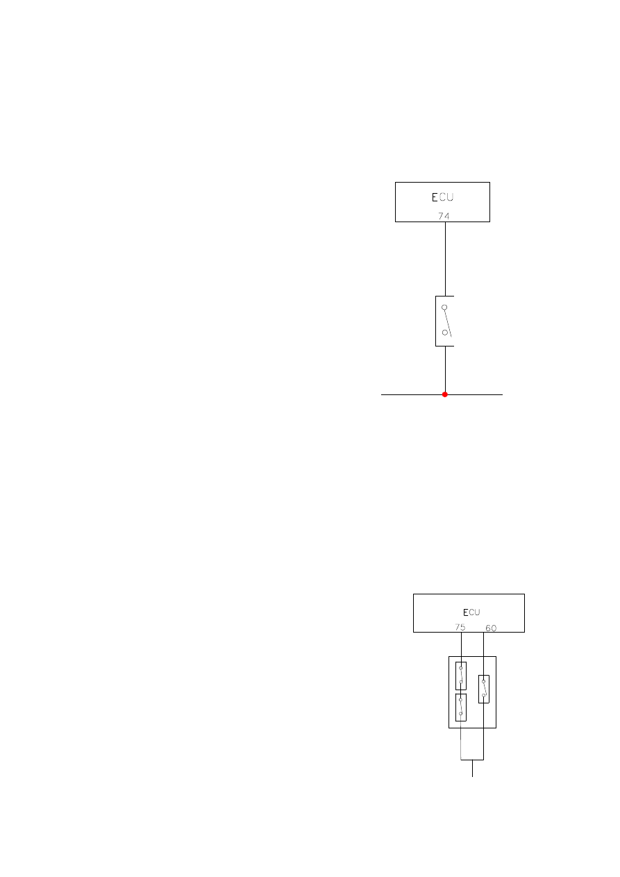
Clutch position switch provides ECU with the signal of clutch position, but this signal can only 

be used to distinguish between disengaging and engaging positions of the clutch. 

17.2 Working principle: 

ECU  provides  clutch  position  switch  with  a  12V  power  supply;  when  the  clutch  is  under 

disengaging  state,  the  power  supply  will  ground  and  ECU  will  lose  12V  high  potential  signal,  by 

which the position of the clutch can be judged. 


18. A/C Control 

By  receiving  the  A/C  signal  from  A/C  switch,  ECU  can  control  working  of  A/C  compressor. 

ECU also can receive the signals from high and low pressure switches of A/C to ensure safety of A/C 

system. When A/C signal is sent to ECU through high and low pressure switches, if the low pressure 

switch breaks, ECU  will  not receive the  A/C signal; the  compressor is thus  unable to  work.  If  A/C 

system  has  a  too  high  pressure,  the  high  pressure  switch  will  break  and  A/C  signal  can  not  be 

provided to ECU; so, ECU will immediately cut off the compressor. When system pressure is normal 

or a little higher (medium pressure), the medium pressure switch will cut in; thus, ECU can control 

the fan to run immediately at high speed to ensure a system pressure within the normal range. 

Cut off pressure of the low pressure switch: 0.12Mpa 

Cut-in pressure of the medium voltage switch: 1.6Mpa 

Cut off pressure of the high pressure switch: 3.2Mpa 

Through  evaporator  temperature  sensor  of  the  A/C  system,  ECU 

can also protect the A/C system and prevent evaporator case from 

freezing.  When  the  temperature  provided  by  the  evaporator 

temperature  sensor  is  blow  3.75

,  ECU  will  cut  off  the 

compressor; when the temperature is above this degree, ECU will 

automatically engage the compressor to let it work. 


C

lu

tc

po
siti

on
 s

w

it

ch
 

开关


M

ediu

m

 v

o

lt

ag

sw

it

ch


H

igh

 a

n

d

 l

o

w

 v

o

lt

a

g

sw

it

ch


A/C switch 


Chapter Two Fundamental Principle for Failure Diagnosis of 

Electronic Fuel Injection System


1. Failure Information Records 

The  ECU  monitors  sensor,  actuator,  related  circuit,  malfunction  indicator  and 

battery  voltage  etc.,  and  even  EUC  itself  continuously.  At  the  same  time,  the  ECU 
inspect  the  reliability  test  on  sensor  signal  output,  actuator  driving  signal  and  internal 
signal  (e.g.:  closed  loop  control,  knock  control,  idle  speed  control  and  accumulator 
voltage  control  etc.).  ECU  will  set  the  malfunction  record  on  RAM  malfunction 
memory  immediately  once  the  malfunction  or  the  unlikelihood  signal  is  detected.  The 
failure information records are stored in the form of diagnostic trouble code (DTC) and 
are displayed in the precedence order of occurrence of the failures.   


Failures can  be divided  into “stable state failures” and  “random  failures” (for example, 
caused  by  transient  open  circuit  of  wires  or  poor  contact  of  inserted  parts)  by  failure 
frequency. 

2. Failure State 

Once duration of occurrence of an identified failure exceeds the given stabilization time 
for  the  first  time,  ECU  will  account  it  as  a  stable  failure  and  then  store  it  as  a  “stable 
state  failure”.  If  this  failure  disappears,  it  will  be  stored  as  a  “random  failure”  and 
“non-existent”. If this failure is identified again, it will still be a “random failure”, but a 
“existent” early failure that will not affect average service of the engine.


3. Failure Types 

Short circuit to positive pole of power supply 
Short circuit to ground 
Open circuit (for the case where there are pull-up resistors or pull-down resistors during 
input  stage,  ECU  will  recognize  failure  of  open  circuit  at  input  port  as  that  of  short 
circuit to positive pole of power supply or that of short circuit to ground) 
Signals can not be used 

4. Failure Frequency Counter


For every identified failure, a separate frequency counter numerical value (Hz) will be 
set. 
This  numerical  value  (Hz)  for  frequency  counter  determines  the  time  this  failure 

information record will be stored in memory after the identified failure disappears (after 
troubleshooting).     
When  a  failure  is  identified  for the  first time,  Hz  will  be  set  as  its  initial  value  40.  If 
failure status does not change, then this numerical value will maintain all along. 
Once it is identified that this failure has disappeared and the state has held for a certain 
time, whenever the engine starts with success (its engine speed has exceeded the  value 
at end of starting) once, Hz will decrease by 1. At this point, ECU will believe that this 
failure has disappeared, but the failure information record still exists. 
If a failure (for example, as a result of poor contact) frequently appears and disappears, 
then Hz will increase by 1, but will not exceed its given upper limit value 100. 
If value of Hz has been decreased to zero, the failure information records in this failure 
memory will be completely cleared. 
 

5. Limp Home 

For  some  identified  significant  failures,  when  duration  exceeds  the  given 

stabilization  time,  ECU  will  take  appropriate  software  countermeasures,  for  example, 
closing  some  control  functions  such  as  closed  loop  control  of  oxygen  sensor  etc.  and 
setting  substituted  values  for  some  data that  are considered  to be  suspect  and  so  forth. 
At  this  point,  though  the  working  condition  of  the  engine  is  comparatively  poor,  the 
auto can still run. The purpose to do this is to enable the auto limply run  home or to a 
service station for overhaul, so as to avoid the embarrassment that the auto breaks down 
on  highway  or  afield.  Once  it  is  identified  that the  failure  has  disappeared  and  Hz  has 
fell to below 40, use of normal data will be resumed again.


6. Failure Alert 

In  the  electric  control  system,  when  failure  take  places  in  any  of  such  important 

parts  as  ECU,  absolute  pressure  sensor  in  intake  manifold,  throttle  position  sensor, 
coolant  temperature  sensor,  knock  sensor,  oxygen  sensor,  phase  sensor,  injector,  two 
driver stages of step motor of  idle speed actuator, canister control valve, or fan relay at 
corresponding  failure  location,  ECU  will  give  an  alarm  through  lightening  of  failure 
indicator lamp until this failure location restores. 

7. Readout of Failure 

The  failure  information  records  can  be  called  out  of  ECU  through  a  trouble  diagnosis 
tester.  If  the  failure  relates  to  the  function  of  mixed  air  (fuel  and  air)  proportional 
regulator,  then  the  engine  must  at  least  run  for  4  minutes  before  reading  out  failure 
information  records;  especially  for  failure  in  oxygen  sensor,  be  sure  not to  detect  data 
until the engine runs and warms up. 
-    -

 


Figure 3-1 ISO 9141-2 Standard Diagnostic Connector 

8. Clearing Failure Information Records


After the  failure  is  removed, the failure  information records  in  memory  should  be 

cleared. The diagnostic trouble code can be cleared through the following approaches: 
When  the  numerical  value  of  frequency  counter  in  ECU  reaches  zero,  the  failure 
information records in failure memory will be automatically cleared. 
Employing fault diagnostic tester to clear records of failure with the instruction of “reset 
memory for records of failure”. 
Pulling  out  connectors  of  ECU  or  disconnecting  wires  of  battery  to  clear  records  of 
failure in external ram. 

9. Failure Locating 

After  obtaining  failure  information  records  through  above  means,  only  rough 

location  where  the  failure  takes  place  is  aware,  but  this  does  not  mean  that  the  failure 
has  been  located;  because  the  cause that triggers  a piece  of  failure  information  may  be 
damage  of  electric  element  (such  as  sensor,  actuator  or  ECU  etc.),  lead  break,  lead 
short-circuit to ground or anode of battery, even may be mechanical failure. 


The  failure  is  intrinsic and the result of its  extrinsic representations  is a  variety of 

symptoms. After a symptom is found, first, check for failure information records with a 
trouble  diagnosis  tester  or  based  on  the  flash  code,  after  that,  remove  the  correlated 
failure  in  accordance  with  the  failure  information,  and then  locate  the  failure  based  on 
symptom of the engine.


10. Failure Code Table


No.


DTC


  Explanation


Failure 

class


P0016


Improper relative installation position between camshaft and crankshaft


class5


P0030 

Failure in heating control circuit of upstream oxygen sensor


class31 

P0031 

Too low voltage in heating control circuit of upstream oxygen sensor


class31


Content   ..  102  103  104  105   ..