Chery QQ6 (S21) / S12LHD. Manual - part 96


  Index      Chery     Chery QQ6 (S21) / S12LHD - service repair manual


Search            


Content   ..  94  95  96  97   ..


Chery QQ6 (S21) / S12LHD. Manual - part 96


1.3  Measurement  of  main  journal  clearance:  place 

a  plastic  feeler  gauge  on  the  crankshaft  main 

journal,  tighten  the  main  bearing  shell  cover  to 

specified  torque  and  then  loosen  it,  use  the 

thickness  check  list  on  the  plastic  feeler  gauge  to 

read  the  value.  The  normal  value  should  be: 

0.02-0.06mm.  Use  the  same  method  to  measure 

connecting rod journal clearance.   


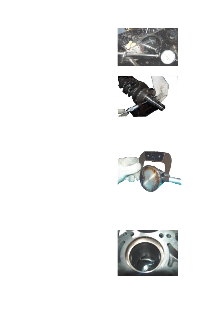
1.4  Measurement  of  crankshaft  axial  clearance: 

tighten  the  main  bearing  shell  cover  to  specified 

torque  and  then  use  a  dial  gauge  to  measure  the 

crankshaft  axial  clearance.  When  measuring,  push 

the  crankshaft  off the  dial gauge first and keep the 

dial  gauge  has  certain  amount  of  compression,  set 

the pointer to zero, and then push the crankshaft to 

the  adverse  direction  and  the  numerical  value 

fetched  from  the  dial  gauge  will  be  the  crankshaft 

axial  clearance.  The  normal  value  should  be 

0.02-0.30mm.  If  exceeding  this  scope,  replace  the 

crankshaft thrust sheet or the crankshaft. 


2. Detection of piston 

2.1  Detection  of  piston  diameter:  use  an  outside 

micrometer  to  measure  the  piston  diameter.  When 

measuring, remember to measure at the place about 

11mm up from lower end of the piston. The normal 

value should be φ72.965±0.009. 


2.2  The  piston  pin  is  of  semi-floating  type,  which 

can  not  be  disassembled  during  maintenance, 

because  it  can  not  be  assembled  using  common 

machining  technique  after  disassembled.  If 

abnormal  noise  occurs  due  to  improper  piston  pin 

clearance, replace the piston assembly. 


2.3 Measurement of piston ring. 

2.3.1  Measurement  of  piston  ring  end  play:  first, 

place the piston ring into cylinder. 


2.3.2  Push  the  piston  head  vertically  against  the 

piston ring in the cylinder and let the piston ring be 

on a plane. 


2.3.3  Use  a  feeler  gauge  to  measure  the  gap 

between  piston  ring  ends  and  the  normal  value 

should be: 0.2mm. 


2.3.4  Measurement  of  piston  ring  side  clearance: 

place the removed  piston ring  into  the ring  groove 

(lean  to  one  side  as  possible)  and  then  place  a 

feeler  gauge  into  the  other  side  to  measure  the 

clearance; certain resistance feeling after the feeler 

gauge  is  placed  in  indicates  that  the  measurement 

with feeler gauge will be correct. The normal value 

should be 0.03mm. Unit: mm 


Contents


First ring

  Second ring  Third ring 

End play


0.2 

0.4 

  / 

Side 

clearance


0.03 

0.03 

  / 

Thickness


1.2 

1.6 

  / 


3.  Measurement  of  roundness  and  cylindricity  of 

cylinder 

3.1  Select  appropriate  cylinder  gauge  and  outside 

micrometer. 


3.2  Use  a  vernier  caliper  to  measure  rough 

diameter of the cylinder hole. 


3.3  Adjust  the  outside  micrometer  to  the  data 

measured  out  by  the  vernier  caliper,  select  the 

splicing  pole  suitable  to  the  range  of  the  cylinder 

gauge, and then set the  outside  micrometer to zero 

according to this data.     


3.4  Place  the  cylinder  gauge  into  the  cylinder  to 

measure;  when  measuring,  the  yawing  angle  of 

cylinder  gauge  should  not  exceed  15º.  Fetch  the 

maximum numerical value. 


3.5  The  measuring  position  of  the  cylinder  gauge 

in cylinder is as shown in the figure. 

Calculation method for roundness: A-B or a-b 

Calculation  method  for  cylindricity:  the  difference 

of  maximum  diameter  subtracting  minimum 

diameter among A, a, B, and b. 

The  normal  value  should  be:  if  roundness  or 

cylindricity  exceeds  the  range,  replace  with  new 

cylinder block or install new cylinder sleeve. 


3.6  Measurement  of  planeness  of  cylinder  block: 

use  steel  rule  and  feeler  gauge  to  measure 

planeness  of  the  cylinder  block.  If  the  planeness 

exceeds the range, replace the cylinder block. 


Upper stop position of piston 

Lower stop position of piston 


III. Installation of Crank-Connecting Rod System 

The  installation  order  is  adverse  to  that  for 

disassembly,  but  care  should  be  taken  for  the 

following matters. 1. Installation of crankshaft thrust 

sheet. 

When  installing  the  crankshaft  thrust  sheet,  leave 

the side with oil groove outwards. 


2. Installation of crankshaft front oil seal 

2.1  Clear  smudge  on  oil  seal  seat  ring,  and  then 

apply a layer of lubricant on the seat ring. 

2.2 Apply a layer of engine lubricant on the oil seal 

lip. 


2.3  Enclose  the  new  oil  seal  with  lubricant  applied 

into  the  special  tool.  Press  the  special  tool  against 

the oil seal seat ring and softly strike to compact. 


3. Installation of crankshaft rear oil seal 

3.1 Clean the oil seal seat ring. Dip engine oil with a 

piece of gauze and then use it to clear the impurities 

inside the oil seal seat ring. 

3.2  Apply  a  layer  of  engine  oil  uniformly  on 

crankshaft  rear  oil  seal  lip  and  a  little  engine  oil 

uniformly on outer ring of oil seal. Envelope the oil 

seal  onto  the  special  tool  and  then  press  it  into  the 

oil seal seat ring. 


Content   ..  94  95  96  97   ..