Chery QQ6 (S21) / S12LHD. Manual - part 76


  Index      Chery     Chery QQ6 (S21) / S12LHD - service repair manual


Search            


Content   ..  74  75  76  77   ..


Chery QQ6 (S21) / S12LHD. Manual - part 76


Chapter Two Decomposition of QR513 Transmission 

I. Decomposition Process for QR513 Transmission     

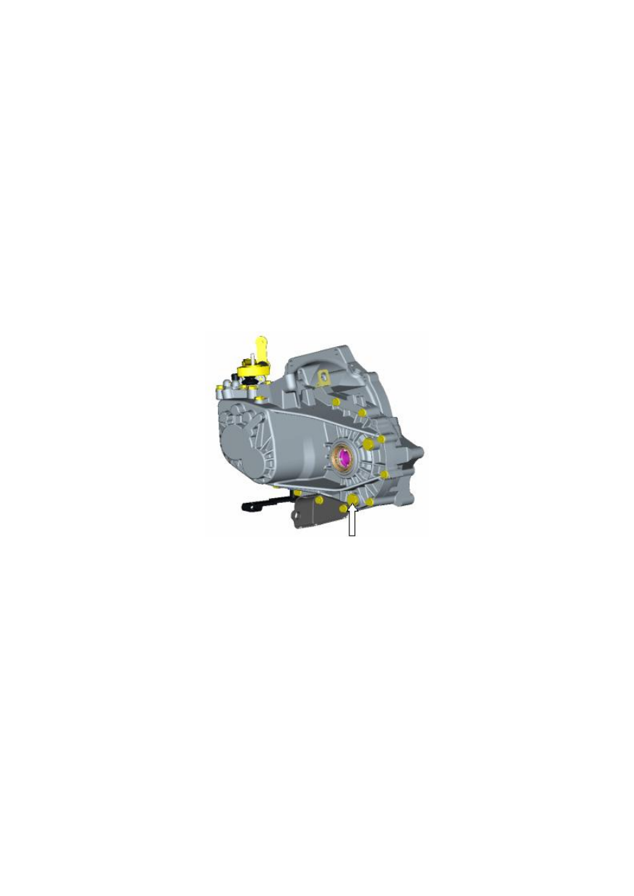
1. Bleeding lubricant in transmission 

First,  drive  the  vehicle  onto  a  maintenance  platform  or  hoist  the  vehicle  and  keep  it  on  a  horizontal 

plane,  screw  off  the  bleeding  plug  as  shown  by  the  arrowhead,  and  then  use  a  clean  container  to 

accommodate lubricant of the transmission to completely bleed the lubricant in the transmission.   


Figure 1 

2. Disassembly of external parts of transmission 

Switch the transmission to NEUTRAL  position;  use an appropriate tool to remove the locating seat  of 

the fork shaft as shown in Figure 2; Connecting bolts for gearshift housing and transmission housing and the 

screws for backup lamp switch and idler shaft.   


                                                                      Screws for idle gear shaft 


                      Bolts-for gearshift housing and                        Backup lamp switch assembly 

                        Transmission    housing (5)  


Figure 2 

3. Separation of gear shift mechanism and transmission 

Remove the gearshift  mechanism assembly  from the place as shown in Figure 3; as a result of sealant, 

the disassembly process may be difficult, so, use such tools as a hand hammer etc. to knock on the bulge at 

flank  of  housing  of  the  gearshift  mechanism,  and  then  take  out  the  whole  gearshift  mechanism  assembly 

until the two  housings  completely separate; remember to be slow when taking  out the  gearshift  mechanism 

assembly, so as to prevent the return spring as shown in the figure from dropping out inside the transmission; 

during disassembly, be careful not to damage the junction planes of the two housings, so as to avoid oil leak 

after re-assembly. 

                              Gearshift mechanism assembly                       


Locating seat of fork shaft 

for all gears (3) 

Assembly of locating 

seat of fork shaft 


Return spring (remember to  prevent 

it from dropping out) 


10 


Figure 3 


4. Disassembly of the connecting bolts for clutch and transmission housings 

Use a tool to remove the connecting bolts  for transmission and clutch  housings as shown in Figure 4. 

Remember to remove the bolts both inside and outside the clutch housing when disassembling, and a sleeve 

with long connecting rod is required when removing the bolts inside the clutch. 


                                              Connecting bolts for transmission and clutch housings 


                                                                    Figure 4 

5. Separation of transmission and clutch housings 

After  the  bolts  for  transmission  and  clutch  housings  are  removed,  separate  clutch  housing  and 

transmission  housing (Figure 5). as a result  of sealant, the separation  process  may be  difficult, so,  use such 

tools as a hand hammer etc. to knock on the bulge at flank of housing of the transmission, and then take out 

the  whole  transmission  housing  until  the  two  housings  completely  separate;  during  disassembly,  be  careful 

not  to  damage  the  junction  planes  of  the  two  housings,  so  as  to  avoid  oil  leak  of  the  transmission  after 

re-assembly. 


11 


                                                      Transmission housing 


  Clutch housing 


                                                                  Figure 5 

6. Separation of interior transmission parts and fork module from the housing 

After transmission housing and clutch housing are separated, keep the clutch housing flat at the place as 

shown in Figure 6, remove the bolts for bracket of reverse gear rocker arm, take out the reverse gear rocker 

arm  assembly  and  the  pin  on  idler  drive,  and  then  take  out  input  shaft,  output  shaft  and  fork  mechanism 

together  (when  taking  out,  gently  shake,  meanwhile,  press  the  driven  gear  of  main  decelerator  along  the 

direction of arrowhead as shown in the figure to take out the assembly of input shaft, output shaft and idler 

as  well  as  fork  mechanism);  when  taking  out,  remember  to  avoid  interference  between  bearing  retainer  of 

output shaft and big gear ring of differential and prevent the bearing retainer from damage. 


              Bolts for reverse gear rocker arm bracket (2 in total) 


Reverse gear rocker arm


Reverse gear idler assembly 

Figure 6 


Content   ..  74  75  76  77   ..