Chery A11. Manual - part 140


  Index      Chery     Chery A11 - service repair manual


Search            copyright infringement  


Content   ..  138  139  140  141   ..


Chery A11. Manual - part 140


Allowable Types of Snap Ring 

Article No. 

Thickness (mm) 

015-1700381AA 2.8 

015-170038AB 2.9 

015-1700381AC 3.0 

015-1700381AD 3.1 

015-1700381AE 3.2 


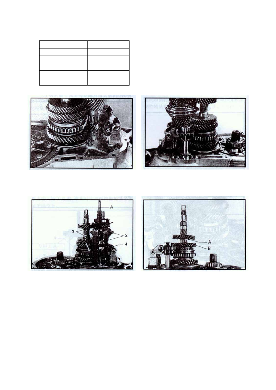
When mounting fork shaft, pay attention to putting the 

counterpoise spring into the fork shaft hole of clutch 

housing.  

When mounting idler shaft, Value X should be equal. 

Mount the fork assy. onto their correct positions 

1— Gear-1 and gear-2 fork 

2— Gear-3 and gear-4 fork 

3— Gear-5 fork guide board and bushing 

4— Reverse gear fork guide board 

When mounting the rear shaft pump baffle A of input 

shaft, notice the position A should be as indicated by 

the figure. Put on new gaskets of fore and rear 

housings, and then the transmission housing.   


15


Screw M7 bolt-1 into the threaded hole as indicated in the 

figure; hold the fork shaft, knock slightly the transmission 

housing with plastic hammer until the bearing comes out 

and at the correct position. Screw in the bolt-2 and fasten 

it with 15Nm torque. Screw in reverse gear bolt and fasten 

it with 20Nm torque. Screw in the fastening bolt of fore 

and rear housings and fasten it with 25Nm torque; fasten 

the rear bearing baffle of input shaft with 15Nm torque.   

Adjustment of gear-5 fork 

Adjust the gear-5 fork by the following procedures 

Notes:  

Never pull out the fork shaft from gear-5 fork bush, 

otherwise the fork and guide board in the housing may 

deviate from their due positions and fall out, thus they 

must be reinstalled.   

Before mounting the shifting shaft, put transmission at 

neutral position. Insert the shifting shaft and big spreader 

spring, and then screw on the plug with 50Nm torque.   

Right screw the fork bush until the bush comes out by 

X=5mm. Pull out the shift shaft completely, left screw 

it and shift to gear 5. Lift slightly the gear-5 connecting 

bush to eliminate the clearance between driving 

mediums.  


Screw in the shifting fixing-seat assy. and fasten it with 

40Nm torque.   

Check the clearance between gear-5 connecting bush 

and connecting tooth of gear-5 driving gear. The 

theoretical value a=1mm. If necessary, screw the gear-5 

fork bush to adjust this clearance to be 1mm.   

Note: when measuring clearance a, move slightly the 

sliding bush and fork to eliminate the free gap.   


16


Support the shifting fork with a tool 12mm thick and 

knock tight the locking plate of gear-5 fork. 

Put on seal washers of rear housing and then mount 

the rear housing assy.   

Apply a coat of grease onto the top of separating 

jogger of clutch and insert it. Shift the gears one by 

one to see whether the they are geared well.   

Special tool 


17

Repair 

Repair of Rear Housing 


1.  Snap ring—separate arm 

2.  Separate arm assy. 

3.  Oil seal assy.—separate shaft 

4. Rear 

housing—transmission 

5.  Fastening screw (CQ1500885) 

6.  Fastening screw of rear housing (CQ1500865) 

7.  Separate shaft of clutch 

8. Release 

spring 

9.  Separate pawl of clutch 

10. Rear cover 

11. Fixing clip 

12.  Draining screw plug 

13. Flap washer 

14. Spring washer 


18


Content   ..  138  139  140  141   ..