Chery A11. Manual - part 10


  Index      Chery     Chery A11 - service repair manual


Search            copyright infringement  


Content   ..  8  9  10  11   ..


Chery A11. Manual - part 10


Usage, repair and maintenance specification of CAC gasoline engine 

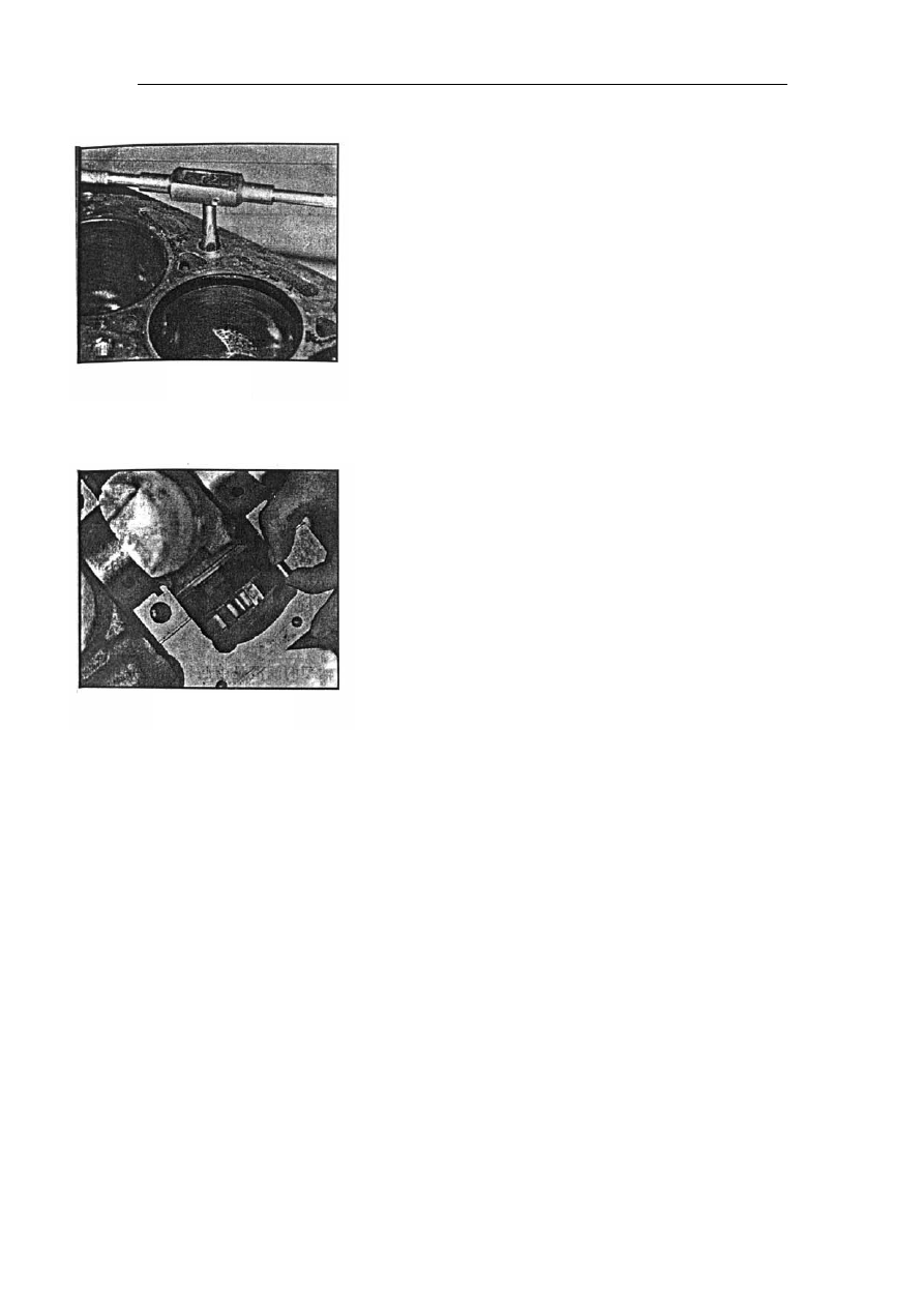
——Nine main bearing bolts are hex head flange side bolts, and 

one is stud. For horizontal engine, the stud is mounted in the left 

threaded hole of the second main bearing cap (see from the front) 

which is for installing the carrier of oil collector. For the vertical 

engine, it should be mounted on the left threaded hole of the 

forth main bearing cap (see from the front).   

Fig. 69 

Before installing the main bearing bolt, engine oil should 

be applied on the joint surface of head end. 

The main bearing bolt and stud should be screwed by hand 

first and tightened to 90—100Nm. 
——The max rotating torque of the crankshaft (with piston rod 

assembly) is 16Nm. 


12】. The removal and installation of oil baffle assembly 


Fig. 70 


Removal: 
——Take out the oil baffle assembly from the right of the back 

end of the cylinder body. 


Installation: 
——Install the oil baffle assembly from the right of the back 

end of the cylinder body (viewed from the front). The oil baffle 

assembly should be tensioned. The spring should be lower than 

the flange surface of cylinder block oil pan. 


41

Usage, repair and maintenance specification of CAC gasoline engine 

13】. Engine oiling system: 

1). The description of the oiling system: 


Fig. 72 

1. 

rotary oil pump assembly        6. oil pump pressure relief valve 

2. 

oil collector                   7. fuel filter 

3. 

oil pan                                              8. oil pressure sensor 

4. 

assistant oil passage of cylinder      9. camshaft 

5. 

main oil passage of cylinder            10. Hydraulic valve lifter 


fig. 71 

    Through oil collector (2), the rotary oil pump(1) 

which is installed in the front end of crankshaft 

draws oil from oil pan (3) and  pressurizes. The 

pressure oil comes into the full flow type oil filter 

through the assistant oil passage (4) on the left of 

cylinder body (viewed from the front). The pressure 

relief valve (6) is installed inside the oil pump case to 

control main oil passage pressure . The pressure 

relief valve will be opened under the pressure within 

440kPa±20kPa. The filtered oil  comes out from 

the center hole of oil filter and    comes into the main 

oil passage of engine (5) through the center hole of 

filter connector. 

    From the main oil passage, oil lubricates the 

main bearing through the bore in the cylinder body 

and lubricates the connecting rod bearing through oil 

passage in the crankshaft. 

        There is a small oil port in the connecting rod 

bearing bore near the exhaust side in the connecting 

rod body. The oil sprays out from this small oil port 

to lubricate the piston pin and cylinder bore. 

    Oil pressure sensor (8) is located near the oil 

filter. It is connected with the main oil passage by a 

inner oil passage. Oil is provided to the third journal 

of camshaft through this oil passage. 

    Other journals of camshaft are lubricated by the 

oil provided by the middle oil passage of camshaft. 

Two sides of the middle oil passage are sealed by 

steel ball. 


Hydraulic lifter oil comes from oil gallery on 

cylinder head, which is supplied from oil channel on 

camshaft neck   

    The oil provided by the oil port inside the 

hydraulic valve lifting rod lubricates the contact face     

of valve rocker and hydraulic valve lifting rod. 

                                                                                The oil to lubricate the rocker carrier is provided 

by the oil passage of cylinder head. 

                                                                                                The  contact  face  of  the  tip  end  of  valve  and 

rocker is lubricated by splashing. 


42

Usage, repair and maintenance specification of CAC gasoline engine 

2) The removal and installation of oil pan: 


removal: 
——Loosen drain plug and drain oil 
——Loosen eighteen M6×20 bolts 
——Take out the sealing gasket of oil pan 
——Check if the left and right reinforced plates are still 

clipped on the back face of oil pan flange face 


Fig. 73 

Installation: 

A.  crankshaft to oil pump shell   

B.  crankshaft to rear oil seal carrier 


                            fig. 74 

— — Apply locite 598 sealant and G Y409 anaerobic 

sealant on the joint place between flange surface of oil pan 

of cylinder body and oil pump case, and carrier of real oil 

seal.  
——Put the new rubber seal gasket on the cylinder body 

and have the two sides of sealing gasket enter into the 

grooves of carrier of real oil seal and oil pump. 


——Install the oil pan with the two sides of sealing gasket 

in the grooves of oil pan. 

 
——Screw the bolt by hand (the bolt with washer indicated 

in the left upper figure is precedent.) 


— — Tighten bolts to 5.0 — 8.0Nm according to the 

sequence of the left figure. 

forward

Fig.75 

 
——Replace the sealing gasket of drain plug. Screw in the 

drain plug by hand and tighten to 21—25Nm. 


43

Usage, repair and maintenance specification of CAC gasoline engine 

The removal and installation of oil collector assembly 


removal: 
——Loosen locknut of oil collector assembly and 

take out the nut and flat washer 
——Loosen carrier bolts and take out the bolts。 
——Loosen flange face bolt of oil collector (two ) 

and take out the two bolts with spring washers 


Fig. 76 


sealing plate- filter


Z direction 

Fig. 78 

Fig. 77 

flat washer


tightening torque

 17.0-23.0Nm


screw M8


screw M6×20


oil collector

Tightening torque 8.0-12.0Nm

with spring plate screws(2)


Installation: 
——Install a new sealing gasket of oil collector 

on the flange face of oil pump and then install oil 

collector assembly. Screw two bolts with gasket 

by hand. 

 
— — Screw the oil collector carrier into the 

cylinder body with M8 bolt. At the same time, 

hitch the carrier into the stud which is in the left 

of the second bearing cap. Install the flat washer 

and screw in the nut by hand. 

 
——Tighten the flange face bolt of oil collector 

to 8.0—12.0Nm. 

 
——Tighten carrier bolt to 17—23Nm 

 
——Tighten the locknut to 17—23Nm 


44


Content   ..  8  9  10  11   ..