Acura RSX Honda Integra. Manual - part 488


  Index      Acura     Acura RSX Honda Integra - service repair manual 2002-2006 year


Search            


Content   ..  486  487  488  489   ..


Acura RSX Honda Integra. Manual - part 488


02

03

04

YES

NO

YES

NO

23-84

SRS

DTC Troubleshooting (cont’d)

BLK

BLU/RED

BLK

RED/BLU

FRONT PASSENGER’S SEAT BELT
BUCKLE SWITCH 3P CONNECTOR

FLOOR WIRE HARNESS 3P CONNECTOR

BLK

C

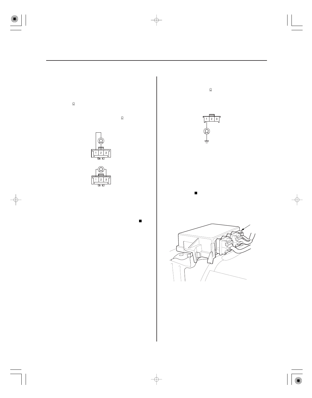
7. Unbuckle the front passenger’s seat belt.

• Check resistance between the No. 1 and No. 2

terminals of the front passenger’s seat belt
buckle switch 3P connector. There should be
0

1

.

• Check resistance between the No. 1 and No. 3

terminals of the same connector. There should
be an open circuit or at least 1 M

.

Go to step 8.

Replace the front passenger’s seat belt buckle

assembly (see page 23-4), and clear the DTC.

8. Check resistance between the No. 1 terminal of the

floor wire harness 3P connector and body ground.
There should be 0

1

.

Go to step 9.

Open in floor wire harness or poor ground

connection at G501. If G501 is OK, replace the floor
wire harness.

9. Disconnect the negative cable from the battery.

10. Disconnect SRS unit connector C (8P) from the SRS

unit.

Terminal side of male terminals

Terminal side of male terminals

Wire side of female terminals

Ar e the r esistance as specif ied?

Is the r esistance as specif ied?

05/06/27 18:10:21 61S6M040_230_0084

05

06

07

08

YES

NO

YES

NO

YES

NO

YES

NO

23-85

FLOOR WIRE HARNESS 3P CONNECTOR

YEL

FLOOR WIRE HARNESS 3P CONNECTOR

ORN

FLOOR WIRE HARNESS
3P CONNECTOR

ORN

SRS UNIT CONNECTOR C (8P)

ORN

FLOOR WIRE HARNESS
3P CONNECTOR

SRS UNIT CONNECTOR C (8P)

YEL

YEL

11. Check resistance between the No. 2 terminal of the

floor wire harness 3P connector and body ground.
There should be an open circuit or at least 1 M

.

Go to step 12.

Short to ground in the floor wire harness;

replace the floor wire harness.

12. Check resistance between the No. 3 terminal of the

floor wire harness 3P connector and body ground.
There should be an open circuit or at least 1 M

.

Go to step 13.

Short to ground in the floor wire harness;

replace the floor wire harness.

13. Check resistance between the No. 7 terminal of

SRS unit connector C (8P) and the No. 3 terminal of
the floor wire harness 3P connector. There should
be 0

1

.

Go to step 14.

Open in floor wire harness or seat subharness

(with BOSE sound system); replace the faulty
harness.

14. Check resistance between the No. 3 terminal of

SRS unit connector C (8P) and the No. 2 terminal of
the floor wire harness 3P connector. There should
be 0

1

.

Replace the SRS unit (see page 23-141).

Open in floor wire harness or the seat

subharness (with BOSE sound system); replace the
faulty harness.

Wire side of female terminals

Wire side of female terminals

Wire side of female terminals

Wire side of female terminals

Is the r esistance as specif ied?

Is the r esistance as specif ied?

Is the r esistance as specif ied?

Is the r esistance as specif ied?

05/06/27 18:10:22 61S6M040_230_0085

01

02

03

S6M6A00K79100081096FAAT00

DTC 9-6:

Special Tools Required

YES

NO

YES

NO

23-86

SRS

DTC Troubleshooting (cont’d)

A

A

A

Faulty Left Front Impact Sensor

• SRS inflator simulator 07SAZ-TB4011A
• SRS simulator lead H 07YAZ-S3AA100

1. Erase the DTC memory (see page 23-23).

2. Turn the ignition switch ON (II), and check that the

SRS indicator comes on for about 6 seconds and
then goes off.

Go to step 3.

Intermittent failure, system is OK at this time.

Go to Troubleshooting Intermittent Failures
(see page 23-24). If another DTC is indicated, go to
the DTC Troubleshooting Index.

3. Turn the ignition switch OFF. Check the

connections between SRS unit connector A (18P)
and the SRS unit, between the engine
compartment wire harness 2P connector and the
left front impact sensor (see page 23-10) and at
connector C403.

Go to step 4.

Repair the poor connections and retest. If

DTC 9-6 is still present, go to step 4.

4. Turn the ignition switch OFF. Disconnect the

battery negative cable, and wait for 3 minutes.

5. Disconnect the driver’s airbag 4P connector from

the cable reel (A).

6. Disconnect the front passenger’s airbag 4P

connector from the dashboard wire harness (A).

7. Disconnect both seat belt tensioner 2P connectors

from the floor wire harness (A).

Does the SRS indicator stay on?

Ar e the connections OK ?

05/06/27 18:10:22 61S6M040_230_0086

04

01

*01

*02

YES

NO

YES

NO

23-87

A

A

SRS UNIT CONNECTOR A (18P)

SRS UNIT CONNECTOR A (18P)

8. Disconnect the engine compartment wire harness

2P connector (A) from the left front impact sensor.

9. Disconnect SRS unit connector A (18P) from the

SRS unit.

10. Check resistance between the No. 10 and No. 11

terminals of SRS unit connector A (18P). There
should be an open circuit or at least 1 M

.

Go to step 11.

Short in the engine compartment wire

harness or dashboard wire harness; replace the
faulty harness.

11. Reconnect the battery negative cable.

12. Turn the ignition switch ON (II).

13. Check for voltage between the No. 10 terminal of

SRS unit connector A (18P) and body ground. There
should be 1 V or less.

Go to step 14.

Short to power in the engine compartment

wire harness or the dashboard wire harness;
replace the faulty harness.

(cont’d)

Wire side of female terminals

Wire side of female terminals

Is the r esistance as specif ied?

Is the voltage as specif ied?

05/06/27 18:10:23 61S6M040_230_0087


Content   ..  486  487  488  489   ..