Acura RSX Honda Integra. Manual - part 259
09
*05
−
−
−
−
−
−
YES
NO
YES
NO
YES
NO
14-161
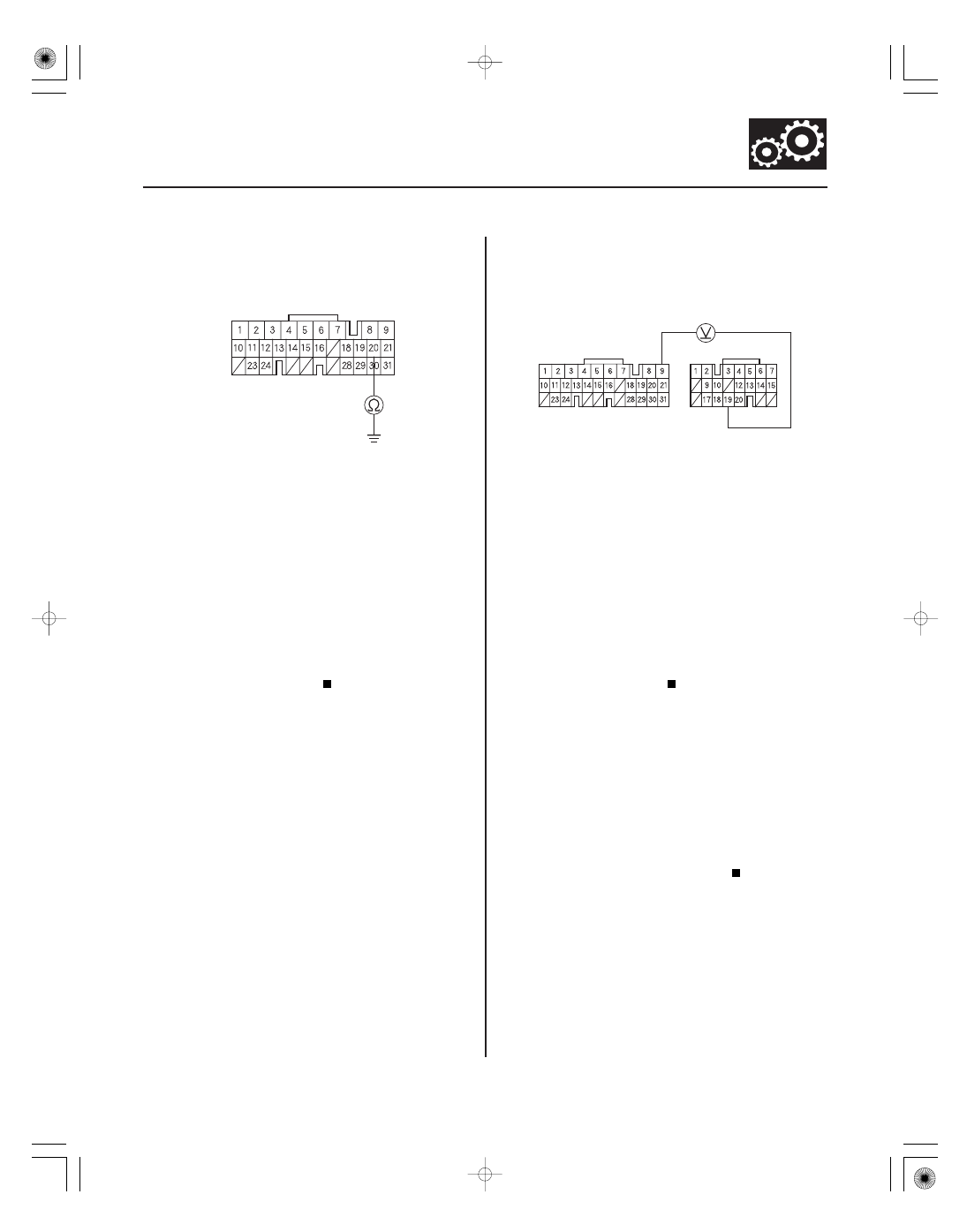
PCM CONNECTOR A (31P)
VCC2 (YEL/BLU)
PCM CONNECTORS
NM (WHT/RED)
LG1 (BRN/YEL)
A (31P)
C (22P)
29. Check for continuity between PCM connector
terminal A20 and body ground.
Repair short to ground in the wire between
PCM connector terminal A20 and the input shaft
(mainshaft) speed sensor connector, then go to
step 31.
Check for loose or poor connections at PCM
connector terminal A20. If the connection is OK,
update the PCM if it does not have the latest
software, or substitute a known-good PCM
(see page 14-11), then recheck. If the symptom/
indication goes away with a known-good PCM,
replace the original PCM.
30. Measure the voltage between PCM connector
terminals C19 and A9.
Repair open in the wire between PCM
connector terminal C19 and the input shaft
(mainshaft) speed sensor connector, then go to
step 31.
Check for loose or poor connections at PCM
connector terminal C19. If the connection is OK,
update the PCM if it does not have the latest
software, or substitute a known-good PCM
(see page 14-11), then recheck. If the symptom/
indication goes away with a known-good PCM,
replace the original PCM.
31. Clear the DTC with the HDS.
32. Start the engine, drive the vehicle in the D position,
and hold the vehicle at speeds over 30 mph (48
km/h) for more than 10 seconds.
33. Monitor the OBD status for P0717 in the DTCs/
Freeze Data in A/T Mode Menu for a pass/fail.
Troubleshooting is completed.
Return to step 1 and recheck.
Wire side of female terminals
Wire side of female terminals
Is ther e continuity?
Is ther e about 5 V ?
Does the r esult indicate a passed?
05/06/27 17:51:23 61S6M040_140_0162