Acura RSX Honda Integra. Manual - part 231
+
+
+
11
2002-2004 Models
PCM Inputs and Outputs
PCM CONNECTOR A (31P)
Terminal
Number
Wire Color
Signal
Description
Measuring Conditions/Terminal Voltage
PCM CONNECTOR B (24P)
Terminal
Number
Wire Color
Signal
Description
Measuring Condition/Terminal Voltage
14-49
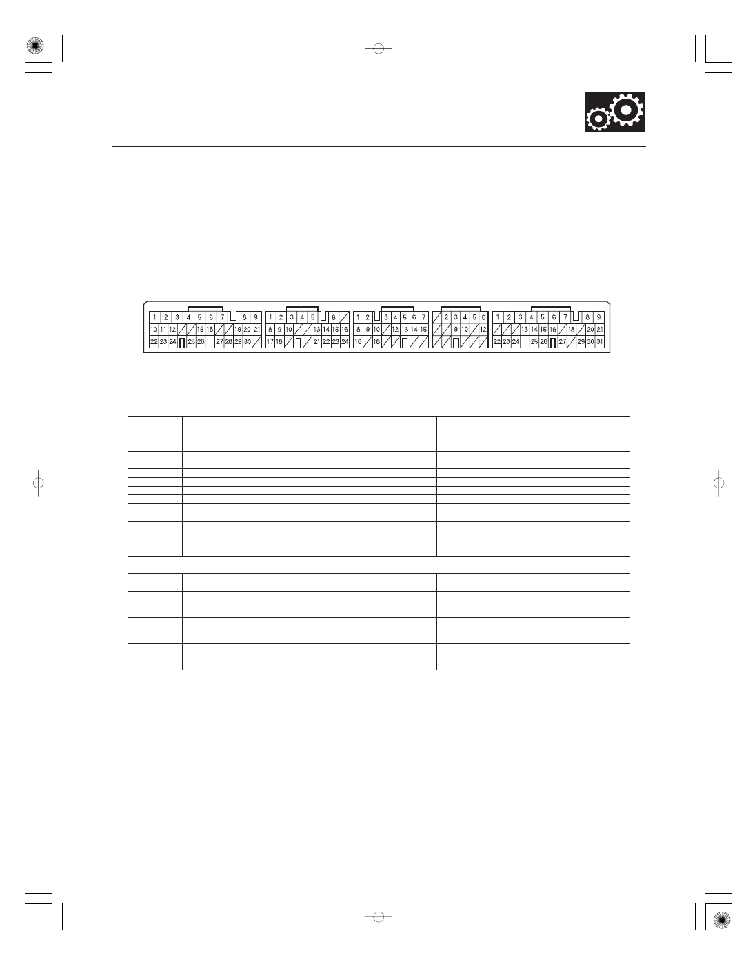
PCM Connector Terminal Locations
A (31P)
B (24P)
C (22P)
D (17P)
E (31P)
The PCM terminal voltage and measuring conditions are shown for the connector terminals that are related to the A/T control system.
A2
YEL/BLK
IGP2
Power supply circuit from main relay
With ignition switch ON (II): Battery voltage
With ignition switch OFF: 0 V
A3
YEL/BLK
IGP1
Power supply circuit from main relay
With ignition switch ON (II): Battery voltage
With ignition switch OFF: 0 V
A4
BLK
PG2
Ground
Less than 1.0 V at all times
A5
BLK
PG1
Ground
Less than 1.0 V at all times
A10
GRN/YEL
SG2
Sensor ground
Less than 1.0 V at all times
A11
GRN/WHT
SG1
Sensor ground
Less than 1.0 V at all times
A20
YEL/BLU
VCC2
Power supply circuit for sensors
With ignition switch ON (II): About 5 V
With ignition switch OFF: 0 V
A21
YEL/RED
VCC1
Power supply circuit for sensors
With ignition switch ON (II): About 5 V
With ignition switch OFF: 0 V
A23
BRN/YEL
LG2
Ground
Less than 1.0 V at all times
A24
BRN/YEL
LG1
Ground
Less than 1.0 V at all times
B14
RED/BLK
LS A
A/T clutch pressure control solenoid
valve A power supply positive
electrode
With ignition switch ON (II): Pulsing signal
B16
BRN/WHT
LS B
A/T clutch pressure control solenoid
valve B power supply positive
electrode
With ignition switch ON (II): Pulsing signal
B24
BLU/YEL
LS C
A/T clutch pressure control solenoid
valve C power supply positive
electrode
With ignition switch ON (II): Pulsing signal
(cont’d)
05/06/27 17:48:46 61S6M040_140_0050