Acura RSX Honda Integra. Manual - part 73


  Index      Acura     Acura RSX Honda Integra - service repair manual 2002-2006 year


Search            


Content   ..  71  72  73  74   ..


Acura RSX Honda Integra. Manual - part 73


01

01

S6M6A00A14426149455FAAT01

02

S6M6A00A14426149455FAAT02

YES

NO

YES

NO

YES

NO

YES

NO

YES

NO

10-18

10-18

Fan Controls

Radiator Fan Switch Circuit
Troubleshooting (Open)

Radiator Fan Switch Circuit
Troubleshooting (Short)

RADIATOR FAN SWITCH 2P
CONNECTOR

GRN/WHT

BLK

RADIATOR FAN SWITCH 2P
CONNECTOR

RADIATOR FAN SWITCH
2P CONNECTOR

GRN/WHT

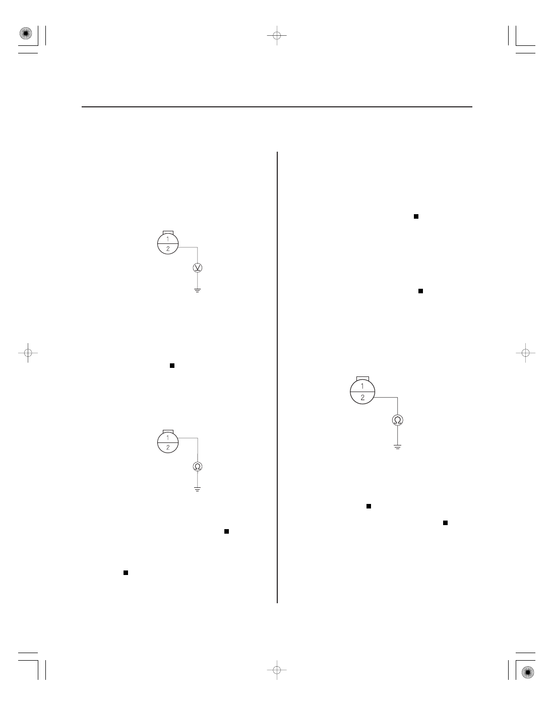
1. Disconnect the radiator fan switch 2P connector.

2. Turn the ignition switch ON (II).

3. Measure voltage between radiator fan switch 2P

connector terminal No. 2 and body ground.

Go to step 4.

Repair an open in the wire between radiator

fan switch 2P connector terminal No. 2 and under-
hood fuse/relay box.

4. Turn the ignition switch OFF, and check for

continuity between radiator fan switch 2P
connector terminal No. 1 and body ground.

Replace the radiator fan switch.

Repair an open in the wire between radiator

fan switch 2P connector terminal No. 1 and body
ground. If the wire is OK, check for a poor ground at
G302.

1. Remove the radiator fan relay from the under-hood

fuse/relay box, and test it (see page 22-62).

Go to step 2.

Replace the radiator fan relay.

2. Remove the radiator fan switch, and test it

(see page 10-19).

Go to step 3.

Replace the radiator fan switch.

3. Disconnect ECM/PCM connector B (24P) and the

under-hood fuse relay box 14P connector.

4. Check for continuity between radiator fan switch 2P

connector terminal No. 2 and body ground.

Repair a short in the wire between radiator

fan switch 2P connector terminal No. 2 and under-
hood fuse/relay box.

Replace the under-hood fuse/relay box.

Wire side of
female terminals

Wire side of
female terminals

Wire side of
female terminals

Is ther e batter y voltage?

Is ther e continuity?

Is the r elay OK ?

Is the r adiator f an switch OK ?

Is ther e continuity?

05/06/27 18:07:06 61S6M040_100_0018

01

*01

S6M6A00A14426149451FEAT01

01

S6M6A00A14426149451KBAT02

10-19

10-19

Radiator Fan Switch Test

Radiator Fan Switch Replacement

B

1

2

A

Terminal

Operation

SWITCH

ON

OFF

Temperature

196

203 °F

(91

95 °C)

5

15 °F (3

8 °C) lower

than the temperature
when it goes on

1

2

A
24 N·m (2.4 kgf·m, 17 lbf·ft)

B

1. Remove the radiator fan switch from the radiator

(see page 10-19).

2. Suspend the radiator fan switch (A) in a container

of water as shown.

3. Heat the water, and check the temperature with a

thermometer. Do not let the thermometer (B) touch
the bottom of the hot container.

4. Measure the continuity between terminal No. 1 and

terminal No. 2 according to the table.

5. Replace, if necessary, and install the radiator fan

switch (see page 10-19).

1. Drain the engine coolant (see page 10-6).

2. Disconnect the radiator fan switch connector, then

remove the radiator fan switch (A).

3. Install the radiator fan switch with a new O-ring (B).

4. Fill the reserve tank and radiator with engine

coolant, and bleed the air from the cooling system
with the heater valve open (see step 7 on page
10-7).

05/06/27 18:07:07 61S6M040_100_0019

S6M6A000000000J1001ZAAT00

05/06/27 18:07:07 61S6M040_100_0020

S6M6A000000000J1101ZCAT00

Fuel and Emissions

Fuel and Emissions Systems

PGM-FI System

VTEC/VTC

Idle Control System

Fuel Supply System

Intake Air System

Catalytic Converter System

PCV System

EVAP System

..................................................

........

.........................

................

.......................................

.......................

..................................................

........

.........................

................

.......................................

.......................

Special Tools

. 11-2

General Troubleshooting Information

. 11-3

DTC Troubleshooting Index

. 11-9

Symptom Troubleshooting Index

. 11-16

System Description

. 11-20

How to Set Readiness Codes

. 11-90

..........................

....................................

.........................

........................

....................................

..............................

....................

.............................
.............................

........................

..............................

.........................

..............................................

................................

Component Location Index

. 11-94

DTC Troubleshooting

. 11-98

MIL Circuit Troubleshooting

. 11-248

DLC Circuit Troubleshooting

. 11-273

Injector Replacement

. 11-277

A/F Sensor Replacement

. 11-279

Secondary HO2S Replacement

. 11-279

CKP Sensor Replacement

. 11-280

ECT Sensor Replacement

. 11-280

CMP Sensor B Replacement

. 11-281

IAT Sensor Replacement

. 11-281

Knock Sensor Replacement

. 11-282

Output Shaft (Countershaft) Speed Sensor

Replacement

. 11-283

ECM/PCM Replacement

. 11-284

..........................

....................................

.........................

........................

............

.................................

.................................

..........................

....................................

.........................

........................

............

.................................

.................................

Component Location Index

. 11-285

DTC Troubleshooting

. 11-286

VTC Oil Control Solenoid Valve

Removal/Test/Installation

. 11-321

CMP Sensor A Replacement

. 11-323

Rocker Arm Oil Control Solenoid

(VTEC Solenoid Valve) Inspection

. 11-323

Rocker Arm Oil Control Solenoid

(VTEC Solenoid Valve) Assembly
Removal/Installation

. 11-324

Rocker Arm Oil Pressure Switch

(VTEC Oil Pressure Switch)
Removal/Installation

. 11-324

..........................

....................................

.............

........................................

........................................

............................

....................................

...................

..........................

....................................

.............

........................................

........................................

............................

....................................

...................

Component Location Index

. 11-325

DTC Troubleshooting

. 11-326

A/C Signal Circuit Troubleshooting

. 11-337

Alternator FR Signal Circuit

Troubleshooting

. 11-339

PSP Switch Signal Circuit

Troubleshooting

. 11-342

Brake Pedal Position Switch Signal

Circuit Troubleshooting

. 11-346

Idle Speed Inspection

. 11-348

ECM/PCM Idle Learn Procedure

. 11-349

..........................

.............

................................

.........................................

........................................

......................................

.................................................

......................................................

..................................................

........

................................

..............................................

................................

.....................

.................................

Component Location Index

. 11-350

Fuel Pump Circuit Troubleshooting

. 11-353

Fuel Pressure Relieving

. 11-360

Fuel Pressure Test

. 11-363

Fuel Tank Draining

. 11-364

Fuel Line Inspection

. 11-365

Fuel Line/Quick-Connect Fitting

Precautions

. 11-368

Fuel Line/Quick-Connect Fitting

Removal

. 11-369

Fuel Line/Quick-Connect Fitting

Installation

. 11-370

Fuel Pressure Regulator Replacement

. 11-373

Fuel Filter Replacement

. 11-374

Fuel Pump/Fuel Gauge Sending Unit

Replacement

. 11-375

Fuel Tank Replacement

. 11-377

Fuel Gauge Sending Unit Test

. 11-379

Low Fuel Indicator Test

. 11-382

..........................

....................................

.........................................

.................................

...................................................

..............................................................

..............................................

.................

...........................
...........................

............

.............

....

..............................................

...................

Component Location Index

. 11-383

DTC Troubleshooting

. 11-384

Throttle Body Test

. 11-403

Throttle Body Cleaning

. 11-403

Throttle Position Sensor Signal

Inspection

. 11-404

Intake Air Bypass Control Thermal Valve

Test

. 11-405

Intake Air Bypass Control Thermal Valve

Replacement

. 11-406

Air Cleaner Removal/Installation

. 11-407

Air Cleaner Element

Inspection/Replacement

. 11-407

Throttle Cable Adjustment

. 11-408

Throttle Cable Removal/Installation

. 11-409

Throttle Body Removal/Installation

. 11-410

Throttle Body Disassembly/Reassembly

. 11-412

IMT (IMRC) Valve Position Sensor

Replacement

. 11-413

IMT (IMRC) Valve Replacement

. 11-413

....................................

....................................

DTC Troubleshooting

. 11-414

....................................
....................................

...............................

....................................
....................................

...............................

DTC Troubleshooting

. 11-417

PCV Valve Inspection

. 11-419

PCV Valve Replacement

. 11-419

..........................

....................................

...........................

............

..............................................

........................

.............................

..............................................

..........................

....................................

...........................

............

..............................................

........................

.............................

..............................................

Component Location Index

. 11-420

DTC Troubleshooting

. 11-422

EVAP Two Way Valve Test

. 11-468

Fuel Tank Vapor Control Valve Test

. 11-469

Fuel Tank Vapor Control Valve

Replacement

. 11-471

EVAP Canister Replacement

. 11-472

FTP Sensor Replacement

. 11-473

EVAP Canister Vent Shut Valve

Replacement

. 11-474

05/06/27 17:29:28 61S6M040_110_0001


Content   ..  71  72  73  74   ..