Acura RSX Honda Integra. Manual - part 58


  Index      Acura     Acura RSX Honda Integra - service repair manual 2002-2006 year


Search            


Content   ..  56  57  58  59   ..


Acura RSX Honda Integra. Manual - part 58


01

02

S6M6A00A18360245611KBAT00

Piston Ring End-Gap
Top Ring:
Standard (New): 0.20

0.35 mm (0.008

0.014 in.)

Service Limit:

0.60 mm (0.024 in.)

Second Ring:
K20A3 Engine:
Standard (New): 0.40

0.55 mm (0.016

0.022 in.)

Service Limit:

0.70 mm (0.028 in.)

K20A2, K20Z1 Engines:
Standard (New): 0.50

0.65 mm (0.020

0.026 in.)

Service Limit:

0.75 mm (0.030 in.)

Oil Ring:
K20A3 Engine:
Standard (New): 0.25

0.65 mm (0.010

0.026 in.)

Service Limit:

0.75 mm (0.030 in.)

K20A2, K20Z1 Engines:
Standard (New): 0.20

0.70 mm (0.008

0.028 in.)

Service Limit:

0.80 mm (0.031 in.)

7-22

Engine Block

Piston Ring Replacement
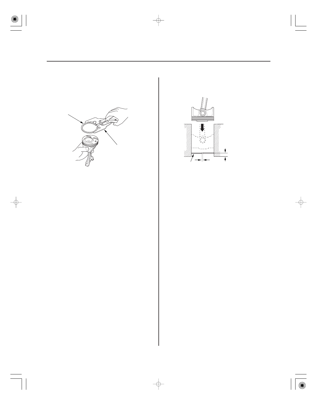
B

A

A

B

15

20 mm (0.6

0.8 in.)

1. Remove the piston from the engine block (see page

7-13).

2. Using a ring expander (A), remove the old piston

rings (B).

3. Clean all ring grooves thoroughly with a squared-

off broken ring or ring groove cleaner with a blade
to fit the piston grooves. The top and 2nd ring
grooves are 1.2 mm (0.05 in.) wide. The oil ring
groove is 2.0 mm (0.08 in.) wide. File down a blade,
if necessary. Do not use a wire brush to clean the
ring grooves, or cut the ring grooves deeper with
the cleaning tools.

NOTE: If the piston is to be separated from the
connecting rod, do not install new rings yet.

4. Using a piston, push a new ring (A) into the

cylinder bore 15

20 mm (0.6

0.8 in.) from the

bottom.

5. Measure the piston ring end-gap (B) with a feeler

gauge:

• If the gap is too small, check to see if you have

the proper rings for your engine.

• If the gap is too large, recheck the cylinder bore

diameter against the wear limits (see page 7-16).
If the bore is over the service limit, the engine
block must be rebored.

01

*01

04

Top Ring Clearance
K20A3 Engine:
Standard (New): 0.035

0.060 mm

(0.0014

0.0024 in.)

Service Limit:

0.13 mm (0.005 in.)

K20A2, K20Z1 Engines:
Standard (New): 0.040

0.065 mm

(0.0016

0.0026 in.)

Service Limit:

0.13 mm (0.005 in.)

Second Ring Clearance
K20A3 Engine:
Standard (New): 0.030

0.055 mm

(0.0012

0.0022 in.)

Service Limit:

0.13 mm (0.005 in.)

K20A2, K20Z1 Engines:
Standard (New): 0.045

0.070 mm

(0.0018

0.0028 in.)

Service Limit:

0.13 mm (0.005 in.)

7-23

A

B

C

A

B

TOP RING (STANDARD):

A: 3.1 mm (0.12 in.)
B: 1.2 mm (0.05 in.)

SECOND RING (STANDARD):
K20A3 engine:

A: 2.8 mm (0.11 in.)
B: 1.2 mm (0.05 in.)

PISTON RING DIMENSIONS:

K20A3
engine

A

B

K20A3
engine

K20A2, K20Z1
engines

K20A2, K20Z1
engines

C

K20A2, K20Z1 engines:

A: 3.4 mm (0.13 in.)
B: 1.2 mm (0.05 in.)

OIL RING GAP

About 90 °

SECOND RING GAP

PISTON PIN

OIL RING GAP

About 45 °

TOP RING GAP and
SPACER RING GAP

6. Install the top ring and second ring as shown. The

top ring (A) has a T1 or R1 mark and the second
ring (B) has a T2 or R2 mark. The manufacturing
marks (C) must be facing upward.

7. Rotate the rings in their grooves to make sure they

do not bind.

8. Position the ring end gaps as shown:

9. After installing a new set of rings, measure the

ring-to-groove clearances:

01

02

*01

S6M6A00A18360200000KCAT00

If the Crankshaft is Already Installed

Tightening Torque
K20A3 Engine:

20 N·m (2.0 kgf·m, 14 lbf·ft)

K20A2, K20Z1 Engines: 29 N·m (3.0 kgf·m, 22 lbf·ft)

7-24

Engine Block

Piston Installation

A

A

B

90 °

1. Set the crankshaft to bottom dead center (BDC) for

each cylinder.

2. Apply new engine oil to the piston, inside of the

ring compressor, and the cylinder bore.

3. Attach the ring compressor to the piston/

connecting rod assembly, and check that the
bearing is securely in place.

4. Position the piston/connecting rod assembly with

the arrow (A) facing the timing belt side of the
engine.

5. Position the piston connecting rod assembly in the

cylinder, and tap it in using the wooden handle of a
hammer (A).
Maintain downward force on the ring compressor
(B) to prevent the rings from expanding before
entering the cylinder bore.

6. Stop after the ring compressor pops free, and

check the connecting rod-to-crank journal
alignment before pushing the piston into place.

7. Check the connecting rod bearing clearance with

plastigage (see page 7-8).

8. Inspect the connecting rod bolts (see page 7-25).

9. Apply engine oil to the bolt threads, then install the

rod caps with bearings. Tighten the connecting rod
bolts.

10. Tighten the connecting rod bolts an additional 90 °.

NOTE: Remove the connecting rod bolt if you
tightened it beyond the specified angle, and go
back to step 8 of the procedure. Do not loosen it
back to the specified angle.

03

04

01

S6M6A00A18316217202MAAT01

If the Crankshaft is Not Installed

Point A

Point B = Difference in Diameter

Difference in Diameter:
Specification: 0

0.1 mm (0

0.004 in.)

7-25

7-25

Connecting Rod Bolt Inspection

A

A

B

35 mm
(1.38 in.)

20 mm
(0.79 in.)

A

B

1. Remove the connecting rod caps, then install the

ring compressor, and check that the bearing is
securely in place.

2. Apply new engine oil to the piston, inside of the

ring compressor, and cylinder bore, then attach the
ring compressor to the piston/connecting rod
assembly.

3. Position the arrow (A) facing the cam chain side of

the engine.

4. Position the piston connecting rod assembly in the

cylinder, and tap it in using the wooden handle of a
hammer (A).
Maintain downward force on the ring compressor
(B) to prevent the rings from expanding before
entering the cylinder bore.

5. Position all pistons at top dead center.

1. Measure the diameter of each connecting rod bolt

at point A and point B.

2. Calculate the difference in diameter between point

A and point B.

3. If the difference in diameter is out-of-tolerance,

replace the connecting rod bolt.


Content   ..  56  57  58  59   ..