Acura RSX Honda Integra. Manual - part 37
02
03
5-12
Engine Assembly
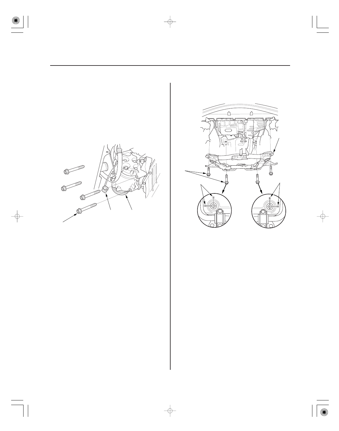
Engine Installation (cont’d)
A
B
8 x 1.25 mm
22 N·m (2.2 kgf·m, 16 lbf·ft)
A
B
B
14 x 1.5 mm
103 N·m
(10.5 kgf·m,
76 lbf·ft)
2. Position the engine under the vehicle. Attach the
chain hoist to the engine, then lift the engine into
position in the vehicle.
NOTE: Reinstall the mounting bolts/support nuts in
the sequence given. Failure to follow this sequence
may cause excessive noise and vibration, and
reduce bushing life.
3. Install the A/C compressor (A), and connect the
compressor clutch connector (B).
4. Install the subframe (A). Align the reference lines
(B) on the subframe with the bolt head center, then
tighten the bolts.
Replace.