Acura RSX Honda Integra. Manual - part 17
*01
S6M6A00A46500000000EAAT00
4-5
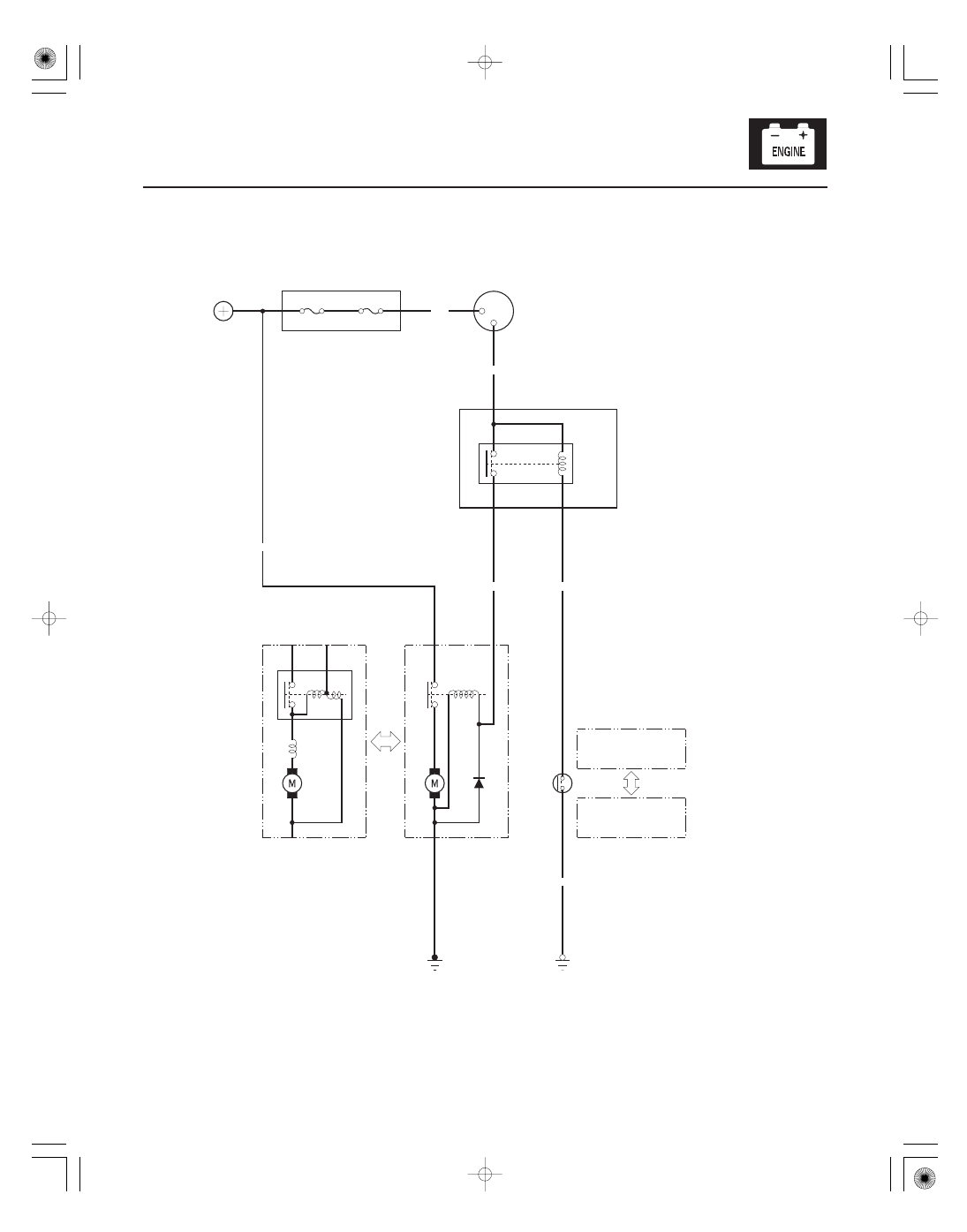
Circuit Diagram
IGNITION SWITCH
BAT
ST
No. 19 (100 A)
BATTERY
UNDER-HOOD FUSE/RELAY BOX
LT GRN
BLK/WHT
BLK/WHT
BLK
S
B
WHT
SOLENOID
M
B
S
ST HOT in START (III)
No. 20*
CLUTCH INTERLOCK SWITCH
(M/T)
(ON: Pedal pressed)
TRANSMISSION
RANGE SWITCH (A/T)
(ON: P, N)
STARTER
(K20A2, K20Z1 engines)
STARTER
(K20A3 engine)
STARTER
CUT
RELAY
UNDER-DASH
FUSE/RELAY
BOX
A/T: G101
M/T: G402
BLK/YEL
* No. 20 (40 A): USA model
No. 20 (50 A): Canada model