Acura CSX. Manual - part 656


  Index      Acura     Acura CSX - P/NO. 61SNR03 - service repair manual 2006-2009 year


Search            


Content   ..  654  655  656  657   ..


Acura CSX. Manual - part 656


*01

*02

*03

YES

NO

From terminal

To terminals

YES

NO

23-335

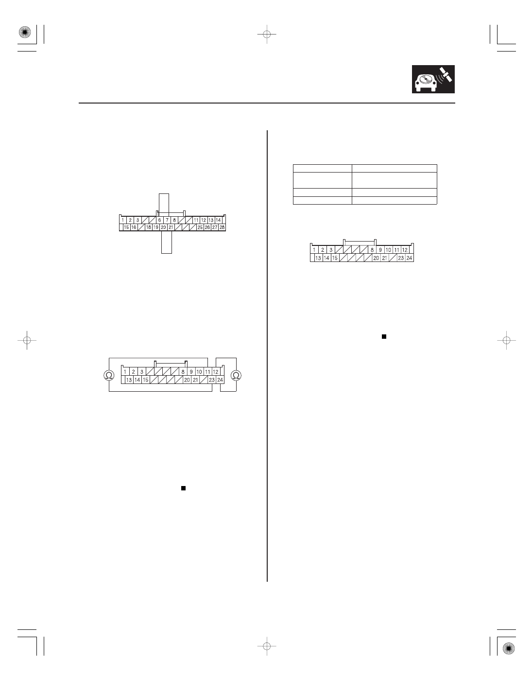
HANDSFREELINK CONTROL UNIT 28P CONNECTOR

NAV
COMM3 (RED)

NAV
COMM4 (WHT)

NAV
COMM2 (GRN)

NAV
COMM1 (BLK)

JUMPER WIRE

JUMPER WIRE

NAVIGATION UNIT CONNECTOR B (24P)

HFL/NAVI
COMM3 (RED)

HFL/NAVI
COMM4 (WHT)

HFL/NAVI COMM2 (GRN)

HFL/NAVI COMM1 (BLK)

NAVIGATION UNIT CONNECTOR B (24P)

13. Connect HandsFreeLink control unit 28P connector

terminals No. 6 and No. 7 with a jumper wire, then
connect the terminals No. 20 and No. 21 with a
jumper wire.

14. Check for continuity between navigation unit

connector B (24P) terminals No. 11 and No. 23 then
check for continuity between terminals No. 12 and
No. 24.

Go to step 15.

Open in the wire between the navigation unit

and the HandsFreeLink control unit. Replace the
affected shielded harness.

15. Disconnect the jumper wire.

16. Check for continuity between the terminals of

navigation unit connector B (24P) according to the
table.

B11 (GRN)

B12 (WHT), B23 (BLK),
B24 (RED)

B12 (WHT)

B23 (BLK), B24 (RED)

B23 (BLK)

B24 (RED)

Short in the wires between the navigation

unit and the HandsFreeLink control unit. Replace
the affected shielded harness.

Go to step 17.

Wire side of female terminals

Wire side of female terminals

Wire side of female terminals

Is ther e continuity?

Is ther e continuity?

08/08/21 14:17:49 61SNR030_230_0338

*04

SNR9ANGK761000N2706FAAT00

Navigation unit

connector

Wire color

YES

NO

YES

NO

DTC 2706:

23-336

23-336

Navigation System

NAVIGATION UNIT CONNECTOR B (24P)

17. Check for continuity between navigation unit

connector B (24P) and body ground according to
the table.

B11

GRN

B12

BLK

B23

WHT

B24

RED

Short to body ground in the wires between

the navigation unit and the HandsFreeLink control
unit. Replace the affected shielded harness.

Replace the HandsFreeLink control unit

(see page 23-388).

NOTE:

• Before you troubleshoot, make sure to follow the

general troubleshooting information (see page
23-266).

• Do this test only when the passenger’s compartment

temperature is between

20 °C (

4 °F) and 70 °C

(158 °F).

1. Clear the hard error code (see page 23-274).

2. Turn the ignition switch to LOCK (0), and then back

ON (II).

3. Check for the hard error code (see page 23-273).

Replace the navigation unit (see page 23-355).

Intermittent failure, the system is OK at this

time.

Gyro Diag: ECU Temp XX °C

Wire side of female terminals

Is ther e continuity?

Is DT C 27 06 indicated?

08/08/21 14:17:49 61SNR030_230_0339

SNR9ANGK761000N2707FAAT00

DTC 2707:

YES

NO

YES

NO

YES

NO

YES

NO

23-337

MIC Diag

NOTE: Before you troubleshoot, make sure to follow the
general troubleshooting information (see page 23-266).

1. Clear the hard error code (see page 23-274).

2. Turn the ignition switch to LOCK (0), and then back

to ON (II).

3. Go into the Diagnostic Menu, and select the Self-

Diagnosis Mode in the Select Diagnosis items
menu (see page 23-297).

4. Select the System Links.

Go to step 5.

Go to step 8.

5. Turn the ignition switch to LOCK (0).

6. Check for poor connections or loose terminals at

the HandsFreeLink control unit 28P connector, the
HFL-navigation microphone 3P connector, and the
navigation unit B (24P) connector.

Go to step 7.

Repair the poor connections or loose

terminals.

7. Check for DTCs with the HDS.

Troubleshoot the indicated DTC.

Replace the HFL-navigation microphone

(see page 23-358).

8. Select the Mic in the System Links.

9. Press the navigation Talk button on the steering

wheel switch, then check the Mic Level (see page
23-311).

Intermittent failure, the system is OK at this

time.

Replace the HFL-navigation microphone

(see page 23-358).

Is the Mic icon r ed?

Ar e the connections OK ?

Is DT C B17 7 5 or B17 7 6 indicated?

Is the micr ophone level OK ?

08/08/21 14:17:50 61SNR030_230_0340

*01

*02

SNR9ANGJ36100000000FAAT09

No picture is displayed

YES

NO

YES

NO

YES

NO

YES

NO

23-338

Navigation System

Symptom Troubleshooting

NAVIGATION UNIT CONNECTOR A (24P)

B BACK UP (WHT)

NAVIGATION UNIT CONNECTOR A (24P)

ACC RADIO (PUR)

NOTE:

• Check the vehicle battery condition first.
• Make sure that the correct DVD color and version are

installed.

• Check any official Honda service website for more

service information about the navigation system.

• Check the connectors for poor connections or loose

terminals.

• Before troubleshooting, make sure you have the

navigation system anti-theft code.

1. Check the No. 23 (10 A) fuse in the under-hood

fuse/relay box and the No. 35 (7.5 A) fuse in the
under-dash fuse/relay box, and reinstall the fuse if
it is OK.

Go to step 2.

Replace the fuse and recheck.

2. Turn the ignition switch to ON (II).

3. Operate the radio and listen to the audio.

Go to step 4.

Refer to audio system troubleshooting.

4. Turn the ignition switch to LOCK (0).

5. Remove the navigation unit (see page 23-355).

6. Measure the voltage between navigation unit

connector A (24P) terminal No. 24 and body ground.

Go to step 7.

Repair open in the wire between the under-

dash fuse/relay box and the navigation unit.

7. Turn the ignition switch to ON (II).

8. Measure the voltage between navigation unit

connector A (24P) terminal No. 14 and body ground.

Go to step 9.

Repair open in the wire between the under-

dash fuse/relay box and the navigation unit.

Wire side of female terminals

Wire side of female terminals

Is the f use OK ?

Can you hear the audio?

Is ther e batter y voltage?

Is ther e batter y voltage?

08/08/21 14:17:50 61SNR030_230_0341


Content   ..  654  655  656  657   ..