Acura CSX. Manual - part 645


  Index      Acura     Acura CSX - P/NO. 61SNR03 - service repair manual 2006-2009 year


Search            


Content   ..  643  644  645  646   ..


Acura CSX. Manual - part 645


*12

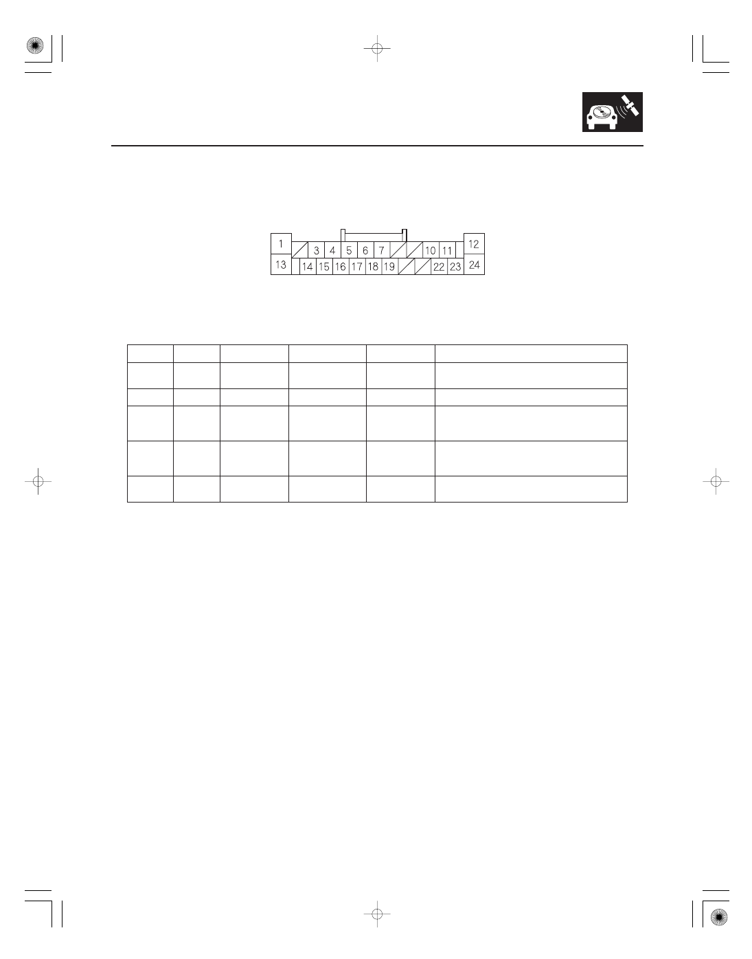
Navigation Unit Inputs and Outputs for Connector A (24P)

Navigation Unit Connector A (24P)

Terminal

Number

Wire Color

Terminal Name

Description

Voltage (about)

Symptom

23-291

1

RED

ILL (

)

Ground for
illumination light

With full dash
lights brightness,
0 V

If open: When brightness = Auto, night mode for the
display is inoperative when lights on.
If short to ground: No change to display.

12

BLK

RADIO GND
(Ground)

Ground for display
unit

0 V

If open: No change to display.
If short to ground: No change to display.

13

GRY

ILL (

)

(Illumination
positive)

Parking light on
signal from dash
and console lights

Light on =
battery voltage,
Lights off = 0 V

If open: When brightness = Auto, night mode for the
display is inoperative when lights on.
If short to ground: Blows fuse No. 14 (7.5 A) in
under-dash fuse/relay box.

15

BLU

VSP
(Vehicle speed
pulse)

Vehicle speed
pulse signal from
ECM/PCM

Pulses 0

5 V:

Average 2.5 V,
when moving

If open: No vehicle speed pulses.
Diagnostic screen Car Status, VSP Navi = 0.
If short to ground: No vehicle speed pulses.
Diagnostic screen Car Status, VSP Navi = 0.

24

WHT

B

(

B power

source)

Continuous power
source

Battery voltage

If open: Screen completely off (no backlight visible).
If short to ground: Blows fuse No. 23 (10 A) in the
under-hood fuse/relay box.

Wire side of female terminals

08/08/21 14:15:46 61SNR030_230_0294

―――

―――

―――

―――

―――

―――

*13

Navigation Unit Inputs and Outputs for Connector B (24P)

Navigation Unit Connector B (24P)

Terminal

Number

Wire Color

Terminal Name

Description

Voltage

(about)

Symptom

23-292

Navigation System

10

GRY

HFL/NAVI COMM SH
(Shield HFL)

Shield for terminal
No. 11, 12, 23, 24

11

GRN

HFL/NAVI COMM2
(HFL communication 2)

Communication
signal for HFL

HFL icon in Navi System Link changes
between red and green

12

WHT

HFL/NAVI COMM4
(HFL communication 4)

Communication
signal for HFL

Solid red HFL icon in Navi System Link

23

BLK

HFL/NAVI COMM1
(HFL communication 1)

Communication
signal for HFL

HFL icon in Navi System Link changes
between red and green

24

RED

HFL/NAVI COMM3
(HFL communication 3)

Communication
signal for HFL

Solid red HFL icon in Navi System Link

: The shielded wires have a heat-shrunk tube insulating the outside of the wire. The color of the insulating tube, typically black or dark gray,

may not match the color of the wire listed on the schematic.

Wire side of female terminals

08/08/21 14:15:46 61SNR030_230_0295

*14

Navigation Unit Inputs and Outputs for Connector C (8P)

Navigation Unit Connector C (8P)

Terminal

Number

Wire Color

Terminal Name

Description

Voltage (about)

Symptom

23-293

1

WHT

B BACK UP

Continuous power
source

Battery voltage

If open: Display picture goes out (display back light
still on). NOTE: System will reboot to enter code
screen.
If short to ground: Blows fuse No. 23 (10 A) in the
under-dash fuse/relay box.

4

BLK

GND

Ground for
navigation unit

0 V

If open: No effect on system.
If short to ground: No effect on system.

7

BRN

BACK LT

Reverse signal of
select laver from
Multiplex
integrated Control
unit (A/T) or
backup light switch
(M/T)

In reverse,
battery voltage:
Otherwise 0 V

If open: Navigation never sees the reverse signal
and back-up camera does not come on when in
reverse. Diagnostic screen Car Status, Back = 0.
If short to ground: Blows fuse No. 10 (7.5 A) in the
under-dash fuse/relay box.

Wire side of female terminals

08/08/21 14:15:46 61SNR030_230_0296

*15

Navigation Unit Inputs and Outputs for Connector D (12P)

Navigation Unit Connector D (12P)

Terminal

Number

Wire Color

Terminal Name

Description

Voltage (about)

Symptom

23-294

Navigation System

1

GRN

NAVI GUIDE

Steering wheel
switch output

4

5 V

(navigation TALK
button pressed)
2.5

3 V

(navigation
BACK button
pressed)

If open: Steering wheel navigation TALK, and
navigation BACK switch/buttons do not work.
If short to ground: Steering wheel navigation TALK,
and navigation BACK switch/buttons do not work.

5

YEL

AC SI

A/C input signal

0-battery voltage
pulses

If open: voice control does not work.
If short to ground: Voice control does not work.

6

RED

AC SO

A/C output signal

0-battery voltage
pulses

If open: A/C voice control does not work.
If short to ground: A/C voice control does not work.

7

BRN

MIC GND

Ground for
microphone signal

0 V

If open: No microphone signal shown in
diagnostics: Navi System Link and Functional Set
up Mic Level.
If short to ground: No effect on voice recognition.

8

YEL

MIC SIG

Microphone output
signal positive

4

5 V (with

navigation TALK
button pressed)

If open: No microphone signal shown in diagnostic
screens: Navi System Link and Functional Setup
Mic Level.
If short to ground: No microphone signal shown in
diagnostic screens: Navi System Link and
Functional Setup Mic Level.

9

GRY

MIC SHIELD

Shield for terminal
No. 7, 8

0 V

If open: No effect on voice recognition.
If short to ground: No effect on voice recognition.

12

BLU

AC CK

Time set sync
signal

0-battery voltage
pulses

If open: A/C voice control does not work.
If short to ground: A/C voice control does not work.

: The shielded wires have a heat-shrunk tube insulating the outside of the wire. The color of the insulating tube, typically black or dark gray,

may not match the color of the wire listed on the schematic.

Wire side of female terminals

08/08/21 14:15:46 61SNR030_230_0297


Content   ..  643  644  645  646   ..