Acura CSX. Manual - part 634
*51
SNR9ANGJ10300000000FAAT37
−
−
−
−
Poor or no sound with XM radio (Audio unit
does display XM channels) (with navigation)
YES
NO
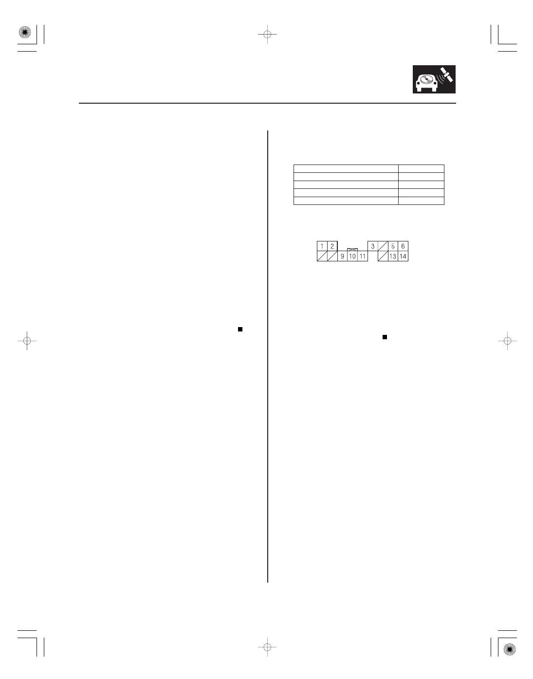
XM receiver connector
Wire color
YES
NO
23-249
XM RECEIVER CONNECTOR A (14P)
NOTE:
• Check the vehicle battery condition first.
• Check the XM radio reception in an open area. Poor
reception/interference can be caused by nearby tall
buildings, mountains, or high-voltage power lines.
• Check the connectors for poor connections or loose
terminals.
• If you can only tune to channel 000, 001, 174, and 247,
make sure the navigation unit is set to channel mode
(see owner’s manual), if it is set to channel mode, call
XM Satellite Radio customer support, and check the
account activation status.
1. Turn the ignition switch to ON (II).
2. Turn on the navigation unit and select XM radio.
3. Check for an error message on the display.
Go to error code list (see page 23-194).
Go to step 4.
4. Turn the ignition switch to LOCK (0).
5. Disconnect navigation unit connector E (14P), USB
adapter unit connector A (14P), and XM receiver
connector A (14P).
6. Check for continuity between XM receiver
connector A (14P) and body ground according to
the table.
A5
WHT
A6
RED
A13
BLK
A14
GRN
Short to body ground in the wire(s) between
the navigation unit and the XM receiver. Replace
the affected shielded harness.
Go to step 7.
Wire side of female terminals
Ar e ther e any messages displayed?
Is ther e continuity?
08/08/21 14:14:14 61SNR030_230_0252