Acura CSX. Manual - part 633
SNR9ANGJ10300000000FAAT34
*42
SNR9ANGJ10300000000FAAT35
+
−
−
−
−
−
−
−
−
−
−
Error code: XM NO SIGNAL or XM ANTENNA
is displayed (with navigation)
XM radio display is blank and no station
information is displayed (with navigation)
YES
NO
YES
NO
YES
NO
YES
NO
YES
NO
23-245
23-245
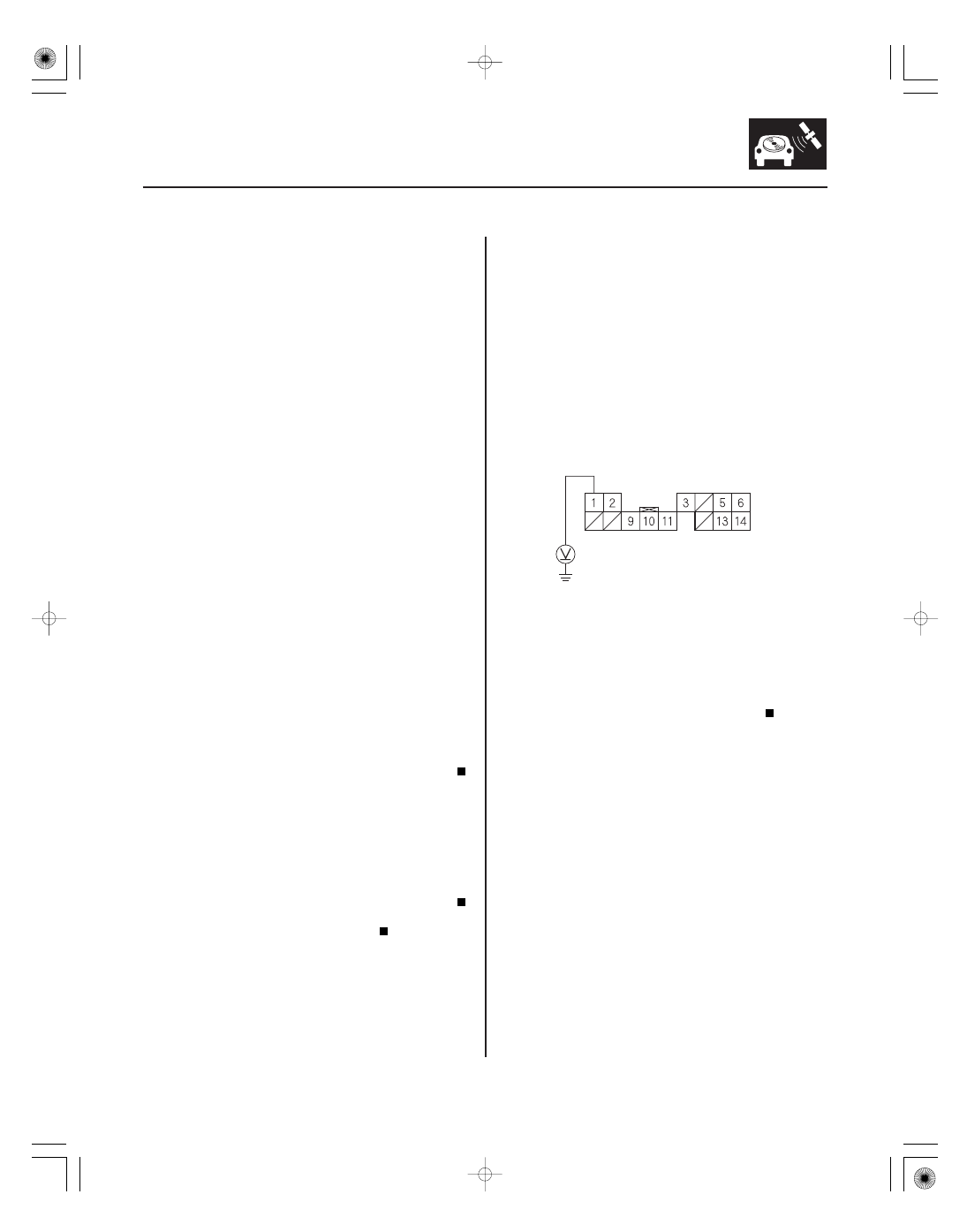
XM RECEIVER CONNECTOR A (14P)
B (BLU)
NOTE:
• Check the vehicle battery condition first.
• Check the connectors for poor connections or loose
terminals.
• Check XM radio reception in an open area. Poor
reception/interference can be caused by tall buildings,
mountains, or high-voltage power lines.
1. Check that the XM receiver connectors properly
connected.
Go to step 2.
Reconnect the connector. If the error message
does not go away, go to step 2.
2. Check the connector at the XM antenna and XM
antenna lead.
Go to step 3.
Reconnect the connector. If the error message
does not go away, go to step 3.
3. Substitute known-good XM antenna (see page
23-264).
Replace the XM antenna (see page 23-264).
Go to step 4.
4. Substitute known-good XM receiver (see page
23-258).
Replace the XM receiver (see page 23-258).
Replace the XM antenna lead.
NOTE:
• Check the vehicle battery condition first.
• Check the connectors for poor connections or loose
terminals.
1. Disconnect XM receiver connector A (14P).
2. Measure the voltage between XM receiver
connector A (14P) terminal No. 1 and body ground.
Go to step 3.
Repair open in the wire between the XM
receiver and the navigation unit connector.
3. Reconnect XM receiver connector A (14P).
Wire side of female terminals
Is the connector connected?
Is the connector connected?
Is the er r or message gone?
Is the er r or message gone?
Is ther e batter y voltage?
08/08/21 14:14:13 61SNR030_230_0248