Acura CSX. Manual - part 600


  Index      Acura     Acura CSX - P/NO. 61SNR03 - service repair manual 2006-2009 year


Search            


Content   ..  598  599  600  601   ..


Acura CSX. Manual - part 600


*12

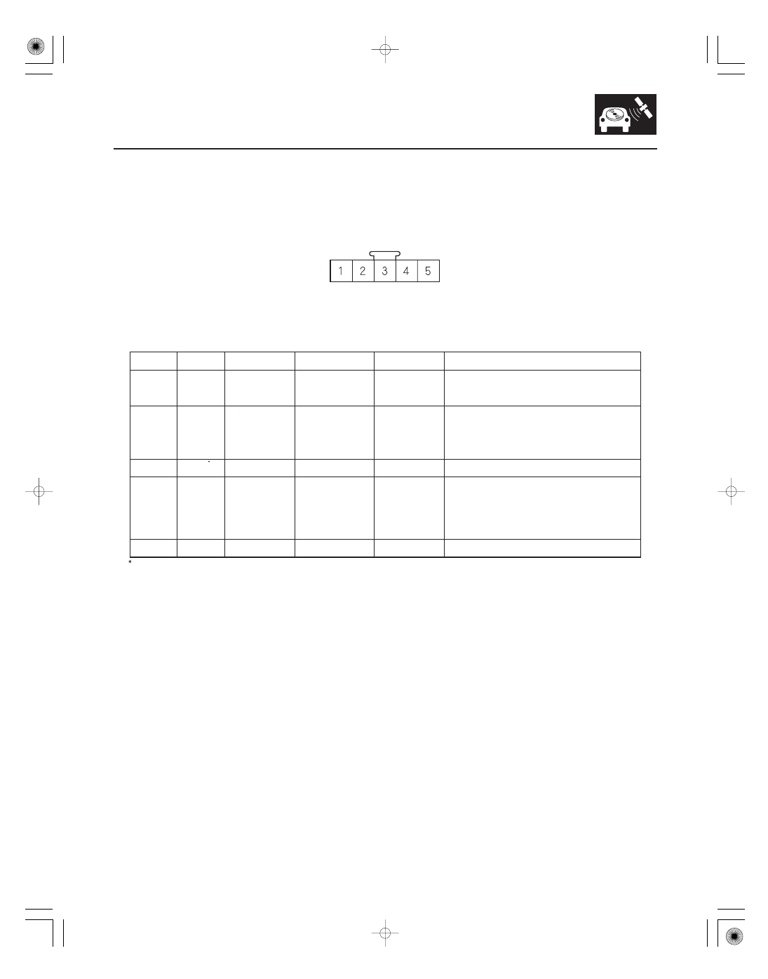
Navigation Unit Inputs and Outputs for Connector D (5P)

Navigation Unit Connector D (5P)

Terminal

Number

Wire Color

Terminal Name

Description

Voltage (about)

Symptom

23-115

1

BRN

MIC GND

Ground for
microphone signal

0 V

If open: No microphone signal shown in
diagnostics: Navi System Link and Functional Set
up Mic Level.
If short to ground: No effect on voice recognition.

2

YEL

MIC SIG

Microphone output
signal positive

4

5 V (with

navigation TALK
button pressed)

If open: No microphone signal shown in diagnostic
screens: Navi System Link and Functional Setup
Mic Level.
If short to ground: No microphone signal shown in
diagnostic screens: Navi System Link and
Functional Setup Mic Level.

3

GRY

MIC SH

Shield for terminal
No. 1, 2, 5

0 V

If open: No effect on voice recognition.
If short to ground: No effect on voice recognition.

4

GRN

NAVI GUIDE

Steering wheel
switch output

4

5 V

(navigation TALK
button pressed)
2.5

3 V

(navigation
BACK button
pressed)

If open: Steering wheel navigation TALK, and
navigation BACK buttons do not work.
If short to ground: Steering wheel navigation TALK,
and navigation BACK buttons do not work.

5

ORN

MIC ADPT

Control signal for
microphone

0 V

If open: No effect on voice recognition.
If short to ground: No effect on voice recognition.

: The shielded wires have a heat-shrunk tube insulating the outside of the wire. The color of the insulating tube, typically black or

dark gray, may not match the color of the wire listed on the schematic.

Wire side of female terminals

08/08/21 14:06:30 61SNR030_230_0118

*13

Navigation Unit Inputs and Outputs for Connector F (5P)

Navigation Unit Connector F (5P)

Terminal

Number

Wire Color

Terminal Name

Description

Voltage (about)

Symptom

23-116

Navigation System

2

BLU

AC CK

Time set sync
signal

0-battery voltage
pulses

If open: A/C voice control does not work.
If short to ground: A/C voice control does not work.

3

YEL

AC SI

A/C input signal

0-battery voltage
pulses

If open: voice control does not work.
If short to ground: Voice control does not work.

4

RED

AC SO

A/C output signal

0-battery voltage
pulses

If open: A/C voice control does not work.
If short to ground: A/C voice control does not work.

Wire side of female terminals

08/08/21 14:06:30 61SNR030_230_0119

―――

―――

*14

Navigation Unit Inputs and Outputs for Connector H (2P)

Navigation Unit Connector H (2P)

Terminal

Number

Wire Color

Terminal Name

Description

Voltage (about)

Symptom

23-117

1

GPS

GPS signal
(5 V in, GPS signal
out)

5 V

If open: GPS icon on screen is white, system links
screen ANT shows NG.
If short to ground: GPS icon on screen is white,
system links screen ANT shows NG.

2

GPS SH

Shield for terminal
No. 1

0 V

If open: GPS icon on screen is white, system links
screen ANT shows NG.
If short to ground: No effect on system.

Terminal side of female terminals

08/08/21 14:06:31 61SNR030_230_0120

01

SNR9ANDJ36100000000EAAT00

23-118

Navigation System

Circuit Diagram

AC CK

AC SO

AC SI

BLU

BACK-UP LIGHT SWITCH (MT)

K-LINE

MICU

A14

PUR

Q14

Q4

GRN

A4

A6

LT BLU

Q8

Q1

WHT

UNDER-DASH FUSE/RELAY BOX

ORN

BRN

10

BRN

3

CABLE REEL

B6

D5

ORN

3

A29

2

1

D4

CABLE REEL

GRN

RED/BLK

BACK

TALK

5

GRY

GRY*

D3

BRN

D1

D2

YEL

GPS

H1

H2

G504

GND

C4

BLK

VSP

BLU

A13

ILL

ILL

F2

F4

RED

YEL

F3

A1

A10

GRY

RED

A17

C1

C7

BRN

NAVIGATION UNIT

VOICE CONTROL SWITCH

8

GRN

680

10 k

2.2 k

ECM/PCM
(VEHICLE
SPEED SIGNAL)

GPS SH
GND

GPS
ANTENNA

MIC SH
GND

MIC
GND

MIC
SIG

NAVI
GUIDE

No. 23 (10 A)
FUSE (In the
under-hood
fuse/relay box)

MIC
ADPT

DASH LIGHTS
BRIGHTNESS
CONTROLLER

No. 14 (7.5 A) FUSE
(In the under-dash
fuse/relay box)

No. 14 (7.5 A) FUSE
(In the under-dash
fuse/relay box)

DASH LIGHTS
BRIGHTNESS
CONTROLLER

B

BACK UP

BACK
LT

No. 35
(7.5 A)
FUSE

B

RADIO

SCTY
RADIO

ACC
RADIO

AUDIO
REMOTE
GND

MULTIPLEX INTEGRATED
CONTROL UNIT (MICU) (AT)

CLIMATE
CONTROL
UNIT

G505

RADIO
GND

A9

BLK

VSP

GPS

MIC
GND

MIC
SIG

MIC
ADPT

E3

BLU

PNK

E9

BUS SH
GND

XM RECEIVER

BRN*

BRN*

E10

A9

A10

A3

(’08 model)

BUS
(GA-NET)

BUS
(GA-NET)

AUDIO
REMOTE
SWITCH

BRN

1

2

5

MICROPHONE

*1:

: Shielding

This shielded wires have a heat-shrunk tube
insulating the outside of the wire. The color
of the insulating tube, typically black or dark gray,
may not match the color of the wire listed on the
schematic.

G2

BUS SH
GND

BUS
(GA-NET)

BUS
(GA-NET)

WHT

WHT

4

08/08/21 14:07:25 61SNR030_230_0121


Content   ..  598  599  600  601   ..