Acura CSX. Manual - part 514


  Index      Acura     Acura CSX - P/NO. 61SNR03 - service repair manual 2006-2009 year


Search            


Content   ..  512  513  514  515   ..


Acura CSX. Manual - part 514


01

SNR9A00K732000Y1150FAAT00

YES

NO

YES

NO

DTC B1150:

22-106

22-106

Multiplex Integrated Control System

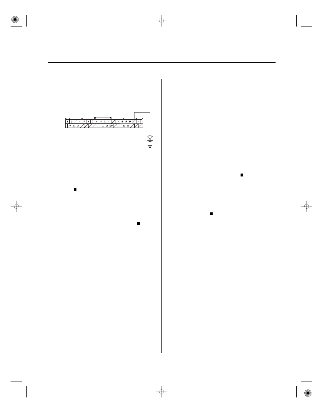
GAUGE CONTROL MODULE (TACH) 36P CONNECTOR

IG1 (BRN)

8. Measure the voltage between gauge control

module (tach) 36P connector terminal No. 17 and
body ground.

Faulty MICU; substitute a known-good

under-dash fuse/relay box and recheck (see page
22-66).

Check No. 10 (7.5 A) fuse in the under-dash

fuse/relay box. If the fuse is OK, check for an open
in the wire between the under-dash fuse/relay box
and the gauge control module (tach), or repair a
short in the wire between the under-dash fuse/relay
box and the gauge control module (tach).

NOTE: If you are troubleshooting multiple DTCs, be
sure to follow the instructions in B-CAN System
Diagnosis Test Mode A (see page 22-93).

1. Clear the DTCs with the HDS.

2. Turn the ignition switch to LOCK (0), and then back

to ON (II).

3. Wait for at least 6 seconds.

4. Check for DTCs with the HDS.

Troubleshooting DTC B1000.

If only DTC B1150 is present, replace the

gauge control module (tach) assembly. If no DTCs
are present, it’s an intermittent failure, the system
is OK at this time. Check for loose or poor
connections at the gauge control module (tach) 36P
connector, and at under-dash fuse/relay box
connector Q (16P).

Communication Bus Line Error

(Bus OFF)

Wire side of female terminals

Is ther e batter y voltage?

Ar e DT Cs B1001, B1008, B1011, B1032, and or
B1900 also indicated with DT C B1150?

08/08/21 14:25:02 61SNR030_220_0108

SNR9A00K711000Y1200FAAT00

SNR9A0DK734000Y1750FAAT00

DTC B1200:

DTC B1750:

YES

NO

YES

NO

22-107

22-107

Communication Bus Line Error

(Bus OFF)

Communication Bus Line Error

(Bus OFF)

NOTE: If you are troubleshooting multiple DTCs, be
sure to follow the instructions in B-CAN System
Diagnosis Test Mode A (see page 22-93).

1. Clear the DTCs with the HDS.

2. Turn the ignition switch to LOCK (0), and then back

to ON (II).

3. Wait for at least 6 seconds.

4. Check for DTCs with the HDS.

Troubleshoot DTC B1000.

If only DTC B1200 is present, replace the

climate control unit. If no DTCs are present, it’s an
intermittent failure, the system is OK at this time.
Check for loose or poor connections at the climate
control unit 32P connector, and at under-dash fuse/
relay box connector Q (16P).

NOTE: If you are troubleshooting multiple DTCs, be
sure to follow the instructions in B-CAN System
Diagnosis Test Mode A (see page 22-93).

1. Clear the DTCs with the HDS.

2. Turn the ignition switch to LOCK (0), and then back

to ON (II).

3. Wait for at least 6 seconds.

4. Check for DTCs with the HDS.

Troubleshoot DTC B1000.

If only DTC B1750 is present, replace the

HandsFreeLink control unit. If no DTCs are present,
it’s an intermittent failure, the system is OK at this
time. Check for loose or poor connections at the
HandsFreeLink control unit 28P connector, and at
under-dash fuse/relay box connector Q (16P).

Ar e DT Cs B1000, B1008, B1011, B1032, and or
B1900 also indicated with DT C B1200?

Ar e DT Cs B1000, B1008, B1011, and B1032 and or
B1900 also indicated with DT C B17 50?

08/08/21 14:25:02 61SNR030_220_0109

SNR9A00K742000Y1900FAAT00

DTC B1900:

YES

NO

22-108

Multiplex Integrated Control System

Communication Bus Line Error

(Bus OFF)

NOTE: If you are troubleshooting multiple DTCs, be
sure to follow the instructions in B-CAN System
Diagnosis Test Mode A (see page 22-93).

1. Clear the DTCs with the HDS.

2. Turn the ignition switch to LOCK (0), and then back

to ON (II).

3. Wait for at least 6 seconds.

4. Check for DTCs with the HDS.

Troubleshoot DTC B1000.

If only DTC B1900 is present, replace the

immobilizer-keyless control unit. If no DTCs are
present, it’s an intermittent failure, the system is
OK at this time. Check for loose or poor
connections at the immobilizer control unit 7P
connector, and at under-dash fuse/relay box
connector Q (16P).

Ar e DT Cs B1000, B1008, B1011, and B1032 also
indicated with DT C B1900?

08/08/21 14:25:02 61SNR030_220_0110

01

SNR9A00J00050641951FCAT00

22-109

MICU Input Test

UNDER-DASH FUSE/RELAY BOX CONNECTOR E (42P)

BLK

BLK

UNDER-DASH FUSE/RELAY BOX CONNECTOR F (34P)

BLK

ORN

UNDER-DASH FUSE/RELAY BOX CONNECTOR G (21P)

1. Before troubleshooting the multiplex integrated control system, troubleshoot the system using B-CAN System

Diagnosis Test Mode A (see page 22-93).

2. Check the No. 10 (7.5 A) fuse in the under-dash fuse/relay box. If the fuse is blown, replace it and go to step 3.

3. Disconnect under-dash fuse/relay box connectors E, F, G, K, and T.

NOTE: All connector views are wire side of female terminals.

08/08/21 14:25:02 61SNR030_220_0111


Content   ..  512  513  514  515   ..